Building construction supporting device

A supporting device and a technology for building construction, which are applied in the direction of construction, building structure, and on-site preparation of building components, etc., can solve the problems of inconvenient support plate height adjustment and inconvenient support plate fixation, so as to improve the lifting operation efficiency and facilitate height Easy to adjust and operate

Active Publication Date: 2018-10-26
包钢集团工业与民用建筑工程有限公司
View PDF6 Cites 7 Cited by
  • Summary
  • Abstract
  • Description
  • Claims
  • Application Information

AI Technical Summary

Problems solved by technology

[0002] A variety of equipment is often used in the construction process, and some equipment needs to be placed on the support device. After retrieval, the patent document with the patent number CN204983727U provides a fitness energy collection device. The support device is composed of a support rod, an intermediate adjustment sleeve, a support rod fixing bolt, an inner fixed leg, a sleeve fixing bolt, a direction adjustment bolt, and a steering base. The common feature is D: one end of the support rod is placed in the middle The inside of the adjustment sleeve, and three or more even...

Method used


Image

  • Building construction supporting device
  • Building construction supporting device
  • Building construction supporting device

Examples


Embodiment 1

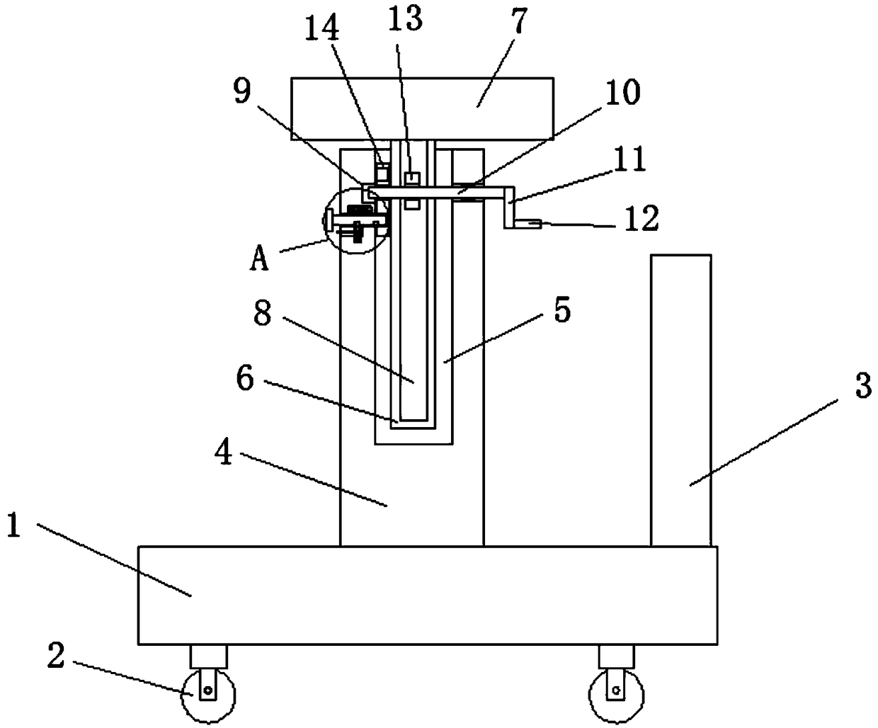
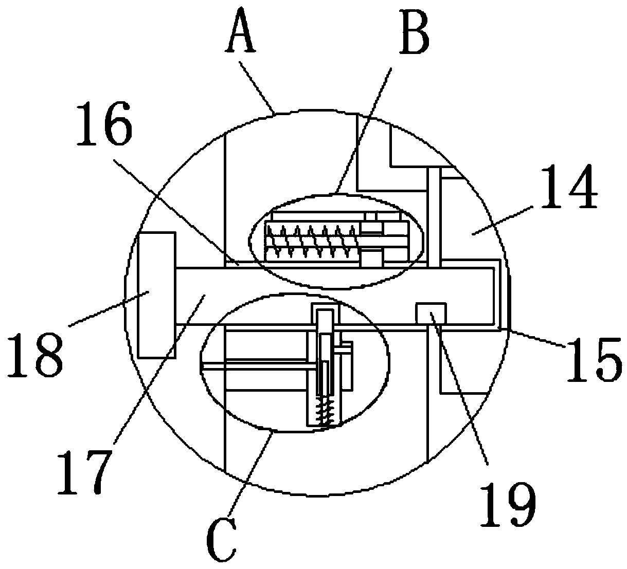
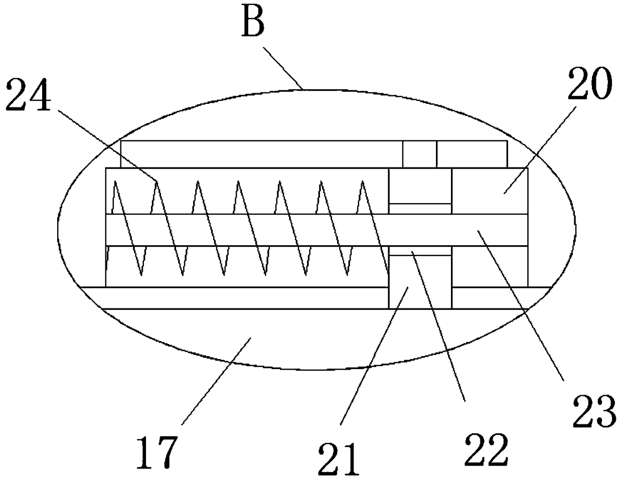
[0027] reference Figure 1-5 In this embodiment, a building construction support device is proposed, which includes a base 1, a plurality of rollers 2 are rotatably installed at the bottom of the base 1, a push plate 3 is fixedly installed on the top of the base 1, and a support column is fixedly installed on the top of the base 1 4. The support column 4 is located on one side of the push plate 3. The top of the support column 4 is provided with a first groove 5, a support rod 6 is slidably installed in the first groove 5, and the top end of the support rod 6 extends to the support column 4 A support plate 7 is welded on top, a rack 8 is welded on one side of the support rod 6, a rotating groove 9 is opened on one inner wall of the first groove 5, and a rotating shaft 10 is rotatably installed in the rotating groove 9. One end of the rotating shaft 10 Extending to the outside of the support column 4 and welded with a rocker 11, a rocker 12 is installed on the side of the rocker...

Embodiment 2

[0031] A building construction support device includes a base 1, a plurality of rollers 2 are rotatably installed at the bottom of the base 1, a push plate 3 is fixedly installed on the top of the base 1, and a supporting column 4 is fixedly installed on the top of the base 1, and a supporting column 4 Located on one side of the push plate 3, the top of the support column 4 is provided with a first groove 5, a support rod 6 is slidably installed in the first groove 5, and the top of the support rod 6 extends above the support column 4 and is welded with a support Plate 7, one side of the support rod 6 is welded with a rack 8; one side of the inner wall of the first groove 5 is provided with a rotating groove 9; a rotating shaft 10 is rotatably installed in the rotating groove 9, wherein the rotating shaft 10 is in the rotating groove 9 It can slide linearly along the axial direction of the shaft 10; one end of the shaft 10 extends to the outside of the support column 4 and is we...


PUM


Abstract

The invention discloses a building construction supporting device which comprises a base. A plurality of rollers are rotatably mounted at the bottom of the base, a pushing plate is fixedly mounted atthe top of the base, a supporting column is fixedly mounted at the top of the base and positioned on one side of the pushing plate, a first groove is formed in the top end of the supporting column, asupporting rod is slidably mounted in the first groove, the top end of the supporting rod extends to the upper portion of the supporting column and is welded with a supporting plate, a rack is weldedon one side of the supporting rod, a rotating groove is formed in the inner wall of one side of the first groove, a rotating shaft is rotatably mounted in the rotating groove, one end of the rotatingshaft extends to the outer side of the supporting column and is welded with a rocker, and a swinging handle is mounted on one side, far away from the rotating shaft, of the rocker. The building construction supporting device is high in practical performance, simple in structure and convenient to operate, the height of the supporting plate is conveniently adjusted, the adjusted supporting plate isconveniently fixed, buildings with different heights are conveniently supported, and use of people is facilitated.

Description

Technical field [0001] The invention relates to the technical field of support equipment, and in particular to a building construction support device. Background technique [0002] Various equipment is often used in the process of building construction, and some of the equipment needs to be placed on support devices. After searching, the patent document with the patent number CN204983727U provides a fitness energy harvesting device. The present invention discloses a building construction support The supporting device is composed of a bracket rod, an intermediate adjusting sleeve, a bracket rod fixing bolt, an inner tooth fixed leg, a sleeve fixing bolt, a direction adjusting bolt, and a steering base. The common features are: one end of the bracket rod is placed in the middle The inner part of the adjustment sleeve is provided with three or more evenly distributed bracket fixing bolts on the upper part of the middle adjustment sleeve; the lower end of the middle adjustment sleeve...

Claims


Application Information

Patent Timeline
IPC IPC(8): E04G25/06
CPCE04G25/06
Inventor 陈云
Owner 包钢集团工业与民用建筑工程有限公司
Why Eureka
Try Eureka