Recovery device of plastic beverage bottle of school canteen
The technology of a recycling device and a beverage bottle is applied in the field of garbage sorting and recycling devices, which can solve the problems of easy breeding of mosquitoes and flies, insufficient space in the canteen garbage storage room, and impact on the dining environment of students.
- Summary
- Abstract
- Description
- Claims
- Application Information
AI Technical Summary
Problems solved by technology
Method used
Image

Examples
Embodiment Construction
[0019] The following will clearly and completely describe the technical solutions in the embodiments of the present invention with reference to the accompanying drawings in the embodiments of the present invention. Obviously, the described embodiments are only some, not all, embodiments of the present invention.
[0020] In describing the present invention, it should be understood that the terms "upper", "lower", "front", "rear", "left", "right", "top", "bottom", "inner", " The orientation or positional relationship indicated by "outside", etc. is based on the orientation or positional relationship shown in the drawings, and is only for the convenience of describing the present invention and simplifying the description, rather than indicating or implying that the referred device or element must have a specific orientation, so as to Specific orientation configurations and operations, therefore, are not to be construed as limitations on the invention.
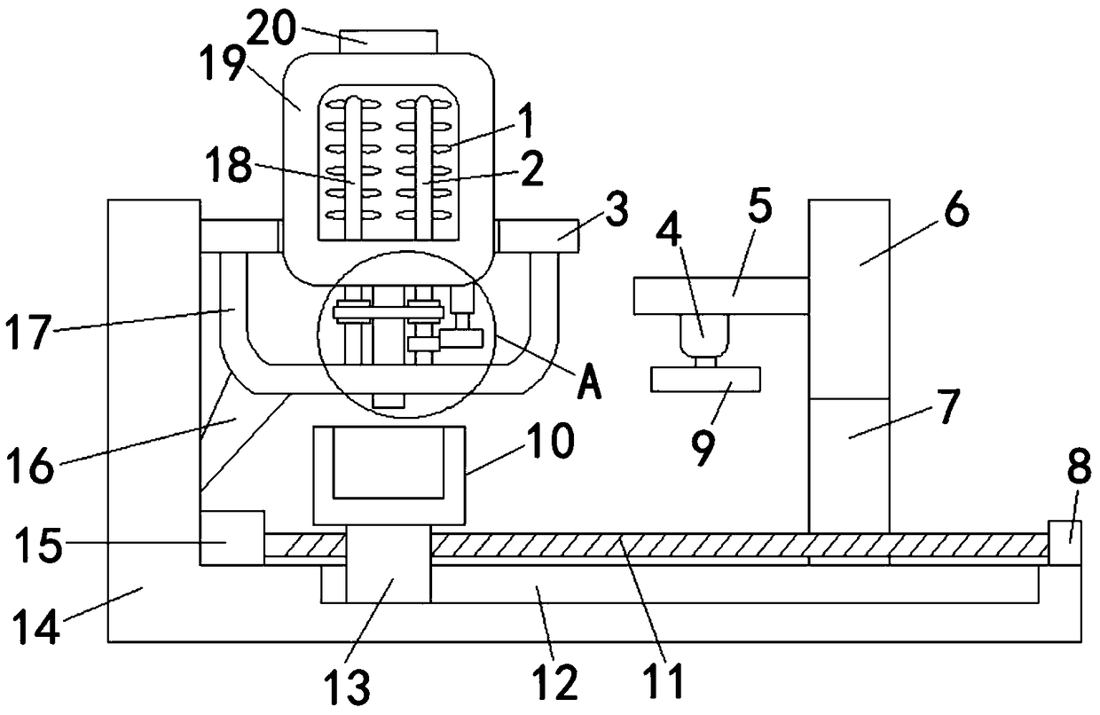
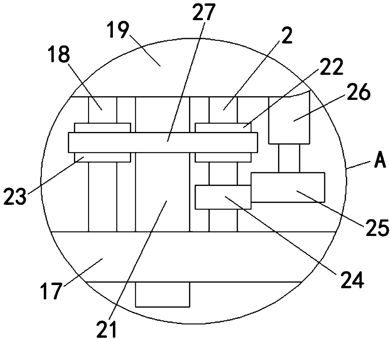
[0021] refer to Figure ...
PUM
 Abstract
Description
Claims
Application Information