Eureka AIR delivers breakthrough ideas for toughest innovation challenges, trusted by R&D personnel around the world.

Extensible Handle for a Cart

a cart and handle technology, applied in the field of handles, can solve the problems of reducing affecting the use of the cart, so as to reduce the cross-sectional area and increase the storage volume or weight of the car

Inactive Publication Date: 2011-04-07
RISNER TOBIN
View PDF11 Cites 5 Cited by
  • Summary
  • Abstract
  • Description
  • Claims
  • Application Information

AI Technical Summary

Benefits of technology

[0004]In view of the foregoing, various exemplary embodiments of an extensible handle suitable for use with any small vehicle pushed or pulled by hand hereinafter described as a cart. The extensible handle(s) described herein do not materially increase the storage volume or weight of the cart; may be adjusted to suit almost any commonly encountered geometry; adaptable for original equipment or for retrofit purposes. In an exemplary embodiment, the extensible handle includes an L-shaped tubular member having a generally arcuate elbow. A clamping assembly is provided for coupling the extensible handle to a cart. The clamping assembly includes a main body, first and second individual clamping members disposed in a side-by-side relationship at opposing ends of the main body. The first clamping member includes a first aperture formed from opposing hemispherical walls of the clamping assembly's main body and is configured to compressively engage an outer circumferential wall of the L-shaped tubular member by reduction of a cross-sectional area of the first aperture.

Problems solved by technology

In many situations, the handles provided with the carts are limited to fixed geometries.
However, extended user propulsion may lead to a variety of ailments such as musculoskeletal pains, muscle sprains and / or aggravation of congenital deformities of the spine.
Even when these fixed propulsion geometries do not materially impact the wellbeing of the user, there still may exist mobility and portability issues which are undesirable, particularly for those involved in an active lifestyle in which the cart needs to be transported in a motor vehicle.

Method used


Image

  • Extensible Handle for a Cart
  • Extensible Handle for a Cart
  • Extensible Handle for a Cart

Examples


Embodiment Construction

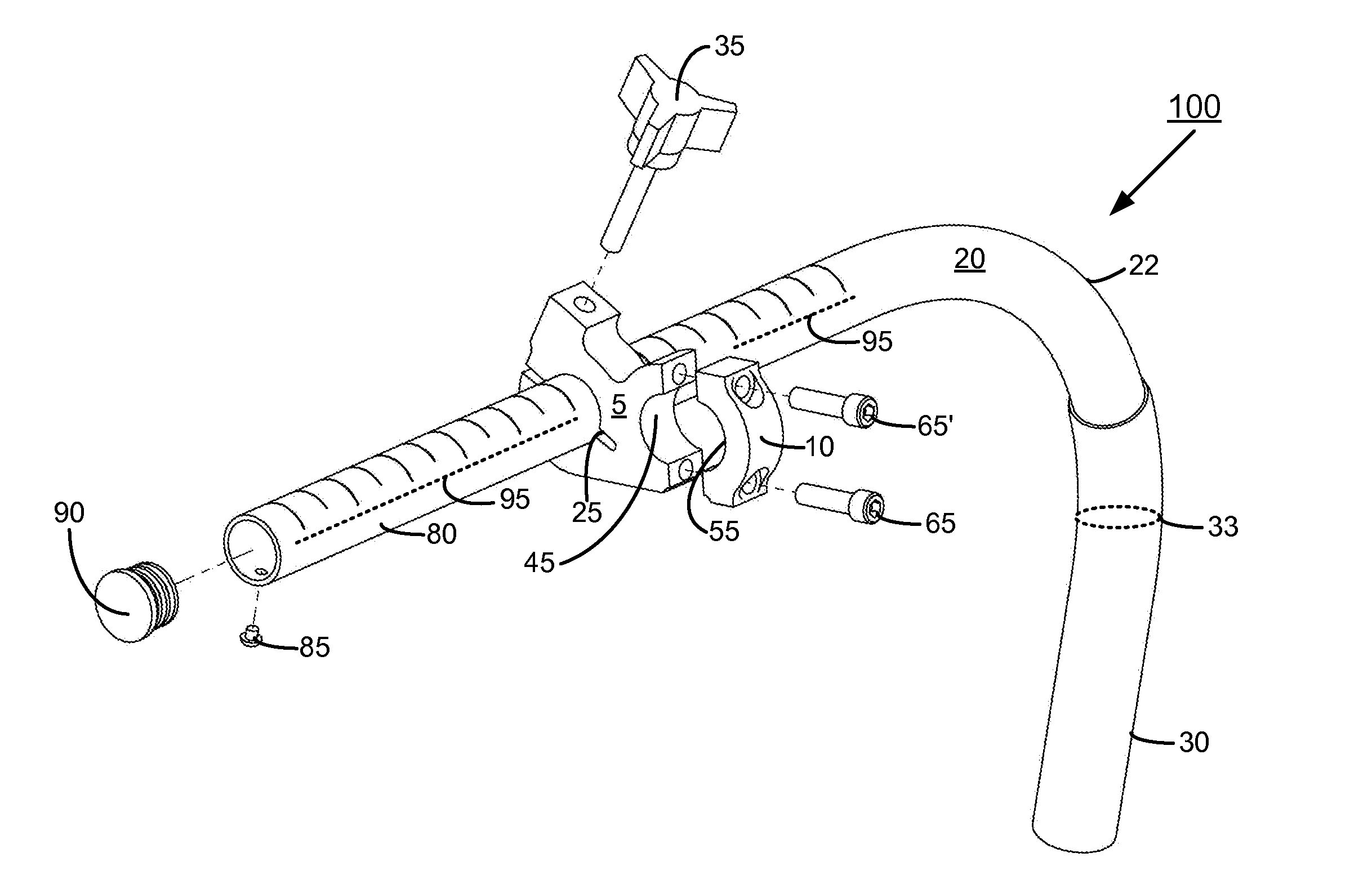
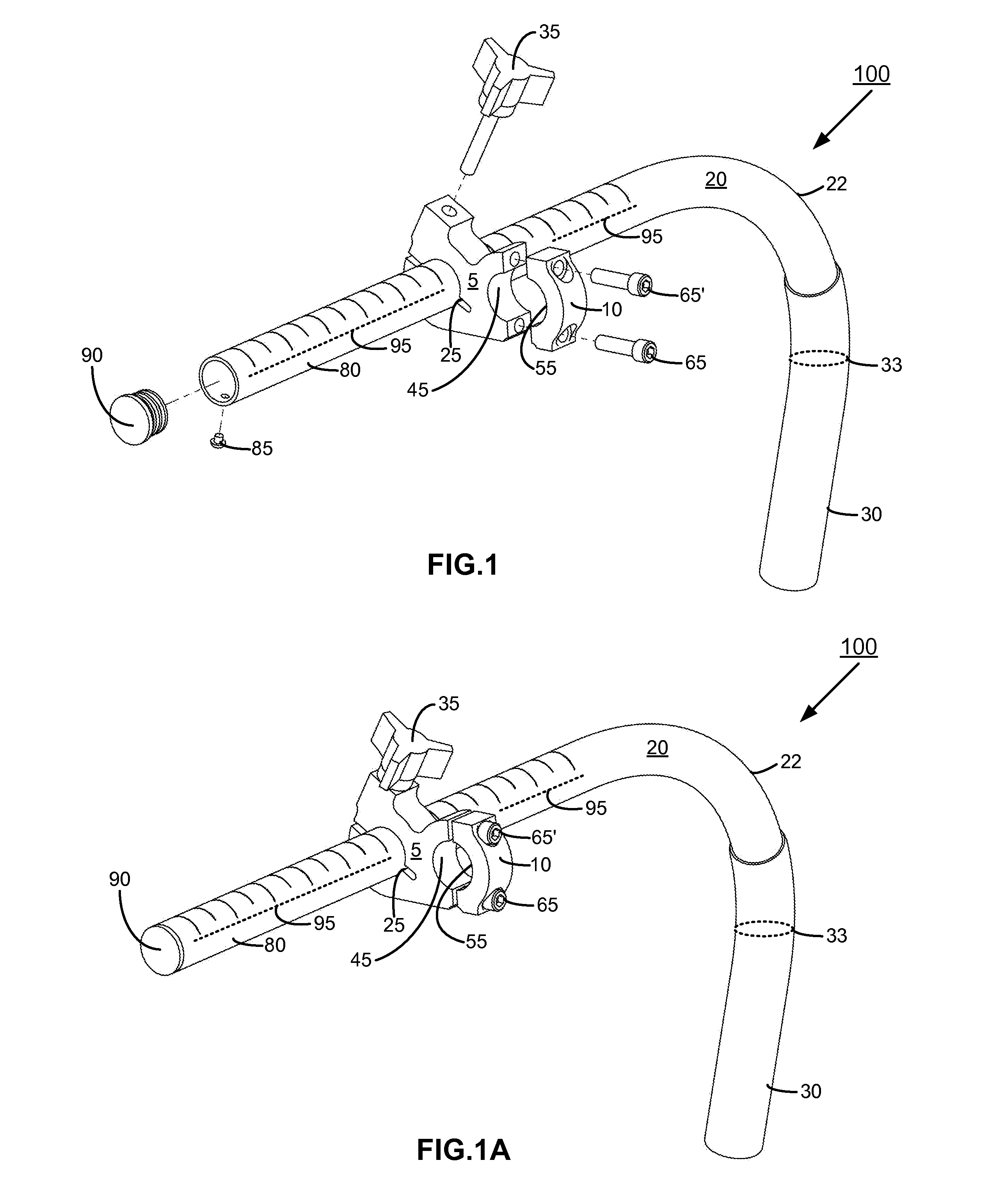
[0024]Various exemplary embodiments of an extensible handle for a cart are disclosed herein. In the following exemplary description, numerous specific details are set forth in order to provide a thorough understanding of the present inventive embodiments. It will be apparent, however, to one skilled in the art that the present inventive embodiments may be practiced without these specific details. In other instances, well-known structures and devices may be shown in block diagram form in order to avoid unnecessarily obscuring the present inventive embodiments. Referring to FIG. 1, an exploded prospective view of an extensible handle 100 in accordance with an exemplary embodiment is depicted. The extensible handle 100 comprises a generally L-shaped tubular member 20. The L-shaped tubular member 20 encompasses a generally arcuate elbow 22, a handle section 30 and a positioning section 80. The handle section 30 encompasses the portion of the L-shaped tubular member 20 in which a user co...


PUM


Abstract

An extensible handle formed from an L-shaped tubular member having a generally arcuate elbow. The extensible handle is coupled to a wheeled cart with a clamping assembly. The clamping assembly includes first and second individual clamping members disposed in a side-by-side relationship at opposing ends of the main body. The first clamping member includes a first aperture formed from opposing hemispherical walls of the main body and is dimensioned to axially receive the L-shaped tubular member therethrough. The second clamping member includes a second aperture formed by a pair of split opposing walls of the main body and is dimensioned to axially receive a longitudinal section of a cart member therethrough. The first and second clamping members are configured to compressively engage longitudinal sections of tubular members passing through their respective apertures by reduction in cross-sectional areas of the apertures

Description

CROSS-REFERENCE TO RELATED APPLICATIONS[0001]Not applicableRELEVANT FIELD[0002]This application is directed generally toward handles and more specifically toward extensible handles for manually powered carts.BACKGROUND[0003]Various carts are known in the relevant art which require a user to provide propulsion by pushing or pulling of the carts. In many situations, the handles provided with the carts are limited to fixed geometries. These fixed geometries may be suitable for short term propulsion of the carts. However, extended user propulsion may lead to a variety of ailments such as musculoskeletal pains, muscle sprains and / or aggravation of congenital deformities of the spine. Even when these fixed propulsion geometries do not materially impact the wellbeing of the user, there still may exist mobility and portability issues which are undesirable, particularly for those involved in an active lifestyle in which the cart needs to be transported in a motor vehicle. Accordingly, there ...

Claims


Application Information

Patent Timeline
Patent Type & Authority Applications(United States)
IPC IPC(8): B25G1/04
CPCB62B5/064Y10T16/473B62B9/20
Inventor RISNER, TOBIN
Owner RISNER TOBIN
Why Eureka
Eureka Blog
Learn More