Annular multistage sedimentation tank for sewage treatment

A technology for sewage treatment and sedimentation tank, which is applied to sedimentation tank, feeding/discharging device of sedimentation tank, sedimentation separation, etc., which can solve the problems of affecting drainage process, high labor intensity of manual cleaning, affecting sedimentation effect, etc.

Active Publication Date: 2020-08-07
义乌市研创工业设计有限公司
View PDF11 Cites 3 Cited by
  • Summary
  • Abstract
  • Description
  • Claims
  • Application Information

AI Technical Summary

Problems solved by technology

[0004] But the above-mentioned three-stage settling tank has the following disadvantages: the settled sludge is not discharged in time, but is first piled up at the bottom of the tank, and after the water is drained, the workers enter the tank to clean up. Clean up in time. When the sludge accumulation is thick, the settl

Method used


Image

  • Annular multistage sedimentation tank for sewage treatment
  • Annular multistage sedimentation tank for sewage treatment
  • Annular multistage sedimentation tank for sewage treatment

Examples


Example Embodiment

[0056] Example 1:

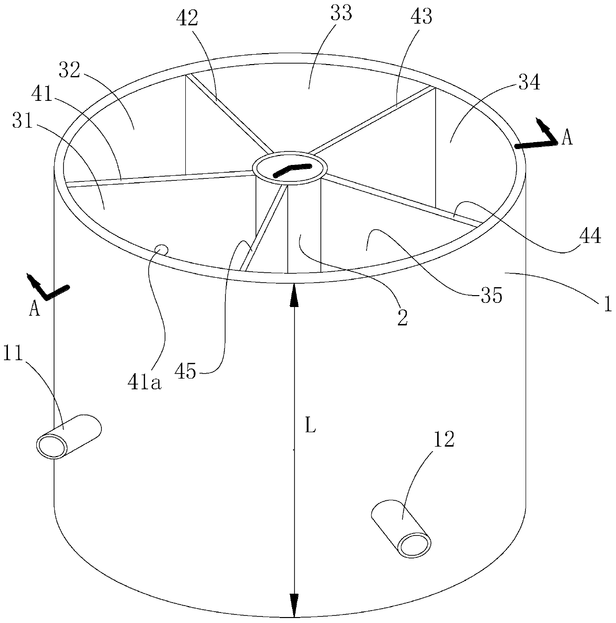
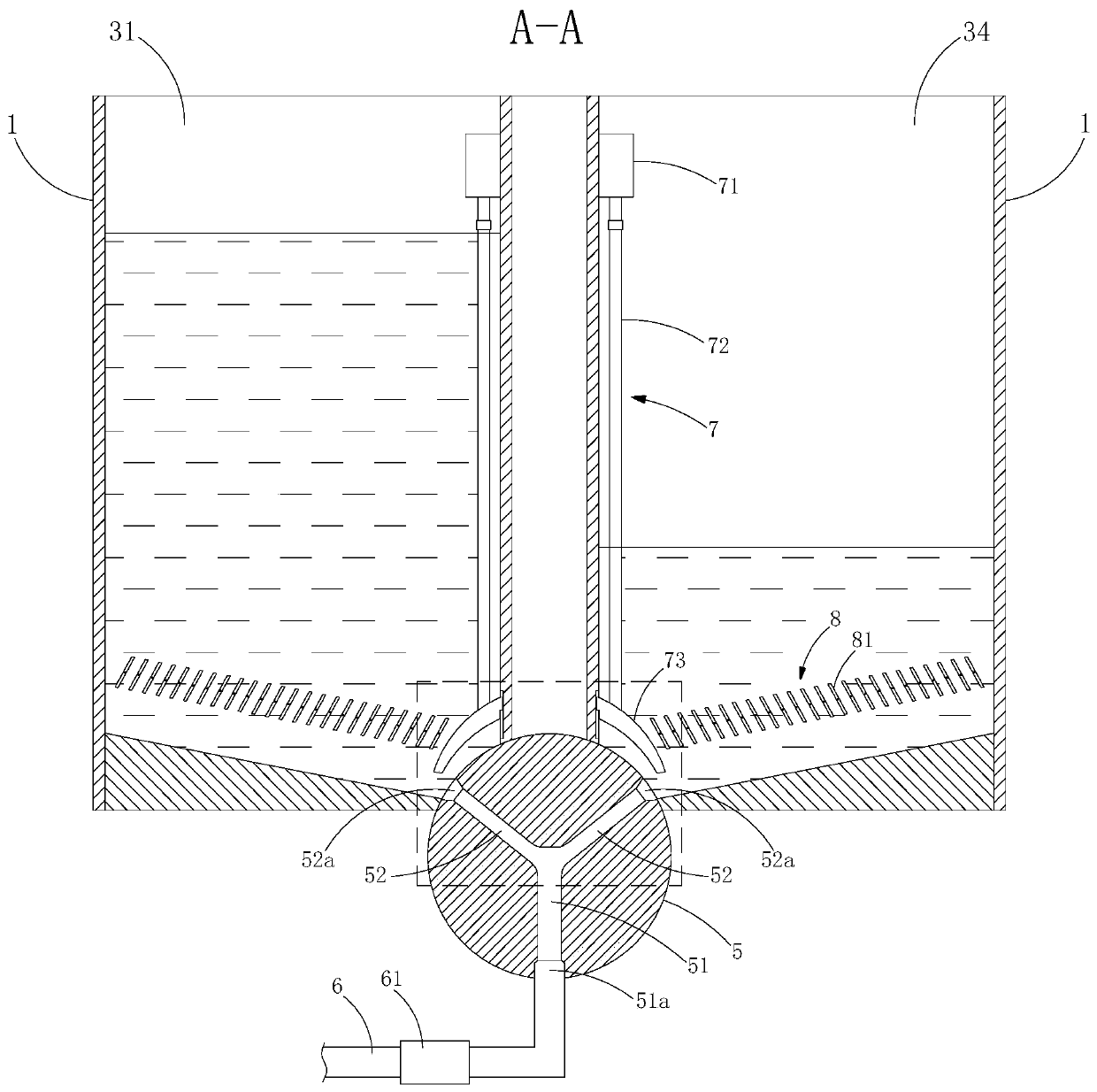
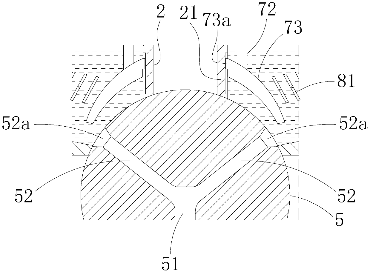
[0057] Such as Figure 1-Figure 6 As shown, this embodiment provides an annular multi-stage sedimentation tank for sewage treatment, which includes an annular outer wall 1, a central column 2, five sedimentation tanks, a sewage channel collection device 5, a sludge conduit 6, a sewage inlet 口adjustment assembly 7 and anti-disturbance assembly 8.

[0058] The annular outer wall 1 is a closed annular wall made of bricks, and its height is L, such as figure 1 As shown; and generally, the inner diameter of the annular outer wall 1 is not less than 1.5m.

[0059] The central column 2 is located in the center of the annular outer wall 1 and is coaxial with the annular outer wall 1. The central column 2 is a hollow structure and is made of concrete, such as figure 1 As shown; and generally, the outer diameter of the center column 2 is not greater than 50cm, and the inner diameter is not less than 10cm.

[0060] The five sedimentation tanks are respectively the first-level ...

Example Embodiment

[0070] Example 2:

[0071] This embodiment provides a method for filtering sewage using the annular multi-stage sedimentation tank of embodiment 1, which includes the following steps:

[0072] S1. Adjust the flow control valve so that the flow control valves of the water inlet pipe 11, the first communicating pipe 41a, the second communicating pipe 42a, the third communicating pipe 43a, and the fourth communicating pipe 44a are opened and the flow rate is kept consistent, while closing Flow control valve of drain pipe 12;

[0073] S2. The sewage to be filtered is introduced into the first sedimentation tank 31 through the water inlet pipe 11; after the sewage enters the first sedimentation tank 31, it will flow into the subsequent sedimentation tanks in turn along the connecting pipes 41a, 42a, 43a, and 44a;

[0074] S3. When the liquid level in the five-stage sedimentation tank 35 rises to h lower than the fourth communicating pipe 44a, close the flow regulating valve of the fourth c...


PUM

PropertyMeasurementUnit
The inside diameter ofaaaaaaaaaa
Outer diameteraaaaaaaaaa

Abstract

The invention discloses an annular multi-stage sedimentation tank for sewage treatment. The annular multi-stage sedimentation tank comprises an annular outer wall, a center column, five settling tanks, a sewage discharge channel gathering device and a sludge guide pipe; the center column is located in the center of the annular outer wall; the five settling ponds are formed in the annular outer wall, distributed around the central column and separated by five partition plates; the sewage discharge channel gathering device is of a spherical structure and is embedded in the bottom of the centralcolumn and the partition plates; the upper half part of the sewage discharge channel collection device is separated by the partition plates and is respectively exposed in the sedimentation tanks, a collection channel and five branch channels are arranged in the sewage discharge channel collection device, one end of each branch channel is provided with a sewage inlet, and the sewage inlets of the branch channels respectively correspond to the sedimentation tanks, so that sludge at the bottom of the tank can be guided into the collection channel; the sludge guide pipe is provided with a sewage pump, and one end of the sludge guide pipe is connected with the collecting channel. According to the invention, sludge at the bottoms of the five settling tanks can be cleaned at the same time as longas the sewage pump on the sludge guide pipe is started, so that the operation is quite convenient.

Description

technical field [0001] The invention relates to the field of sewage treatment, in particular to a settling tank for sewage treatment. Background technique [0002] The drainage system in the foundation pit project often uses multi-stage settling tanks to settle the accumulated water on the site. Its function is to settle the soil and sand in the water, so that the water can be purified to a certain extent, and then discharged into the municipal drainage system. [0003] At present, three-stage settling tanks are usually used. The settlement process is: after the rainwater or groundwater in the drainage ditch flows into the settling tank, it will pass through the three settling tanks of the first, second, and third sets of sedimentation tanks, and then the clean water will be collected by the third settling tank. The sedimentation tank is discharged, and the sludge is deposited on the bottom of each sedimentation tank. After the water is drained, the sludge at the bottom of t...

Claims


Application Information

Patent Timeline
IPC IPC(8): B01D21/02B01D21/24B01D21/34B01D21/00
CPCB01D21/0033B01D21/0042B01D21/02B01D21/245B01D21/34
Inventor 何淑会
Owner 义乌市研创工业设计有限公司
Why Eureka
Try Eureka