Microfluidic device for precise cell control

A microfluidic and device technology, applied in biochemical instruments, enzymology/microbiology devices, bioreactor/fermenter combinations, etc., can solve the prediction and regulation of unfavorable particle inertial migration behavior, complex changes, and inability to form single-row focusing Arrangement and other issues, to achieve the effect of compact space layout, simple operation and high precision

Active Publication Date: 2018-10-30
苏州中芯启恒科学仪器有限公司
View PDF3 Cites 8 Cited by
  • Summary
  • Abstract
  • Description
  • Claims
  • Application Information

AI Technical Summary

Problems solved by technology

However, in a rectangular or trapezoidal cross-section spiral flow channel, the cross-sectional Dean vortices are symmetrically distributed on the upper and lower sides of the flow channel, resulting in multiple equilibrium positions of the particles in the vertical direction, which cannot form a true single-row focusing arrangement.
In addition, the plane extension along the Archimedes spiral leads to the variable curvature of the spiral flow channel, which makes the changes of the inertial lift and Dean drag force on the particles in the fluid extremely complicated, which is not conducive to the prediction and regulation of the inertial migration behavior of particles

Method used


Image

  • Microfluidic device for precise cell control
  • Microfluidic device for precise cell control
  • Microfluidic device for precise cell control

Examples


Embodiment Construction

[0020] The present invention will be described in detail below in conjunction with the accompanying drawings.

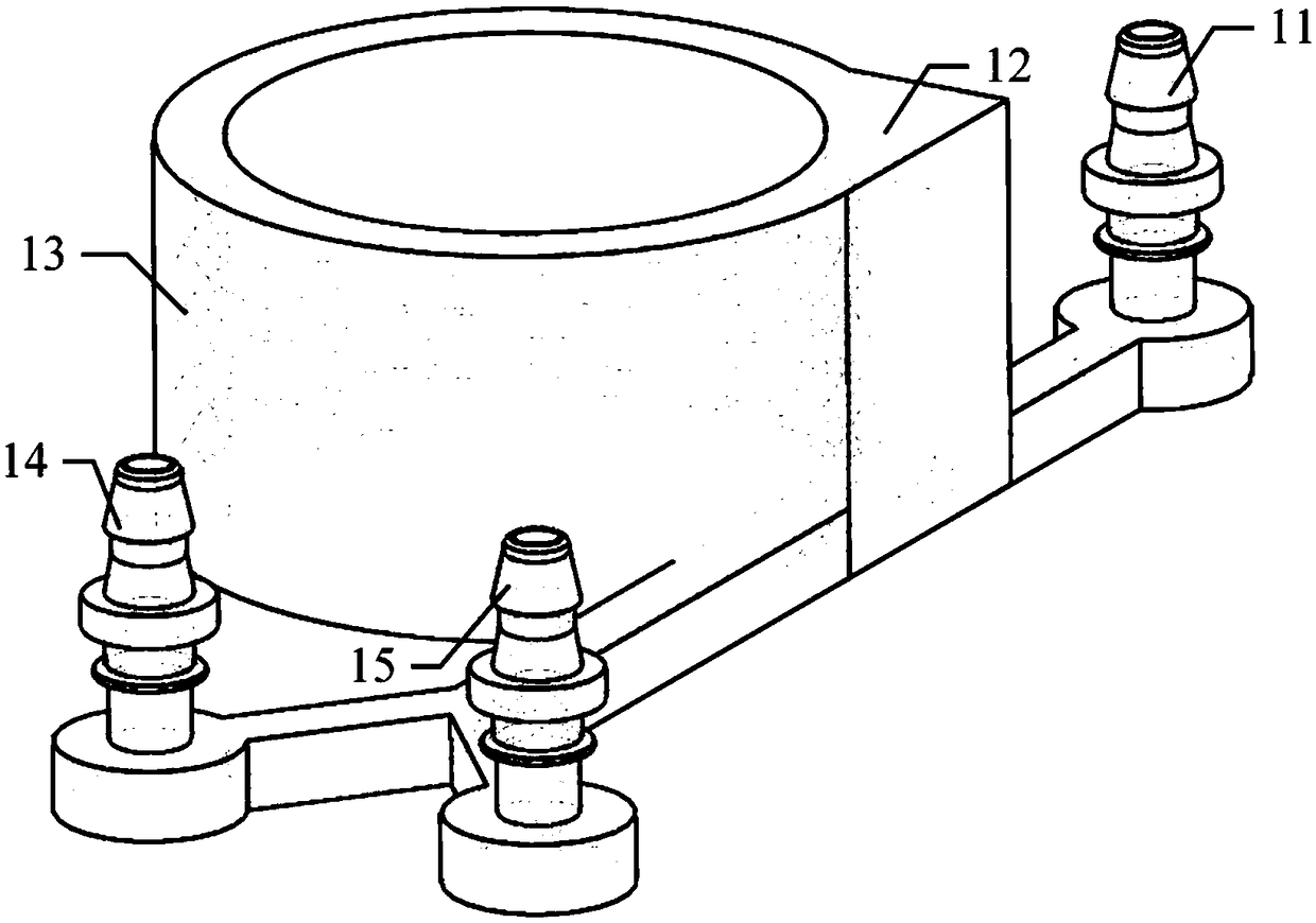
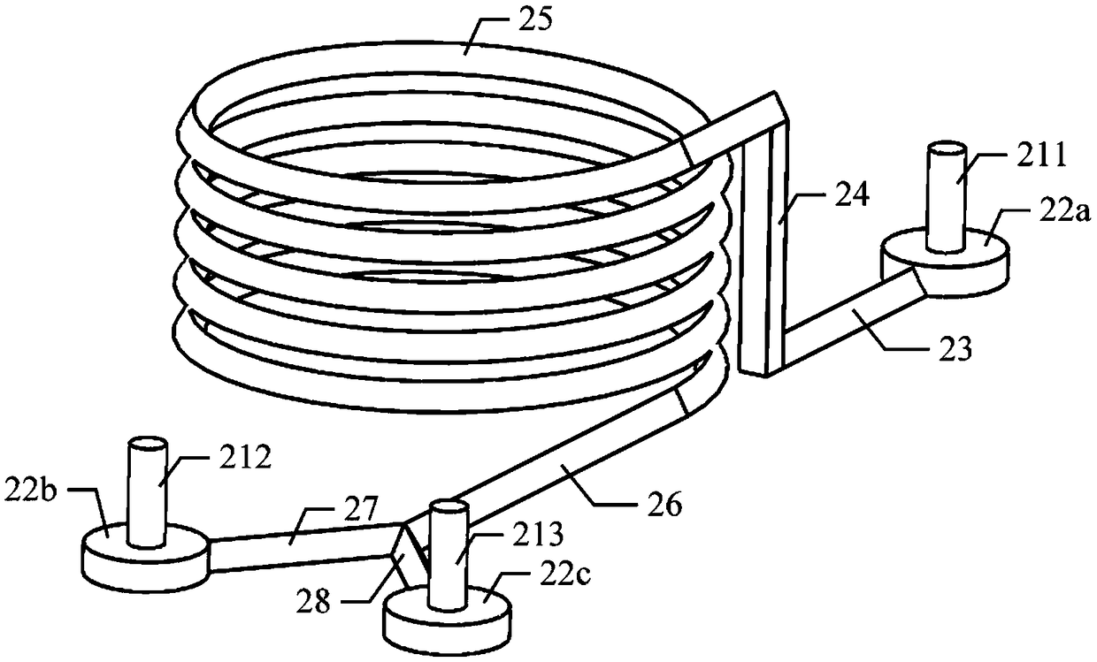
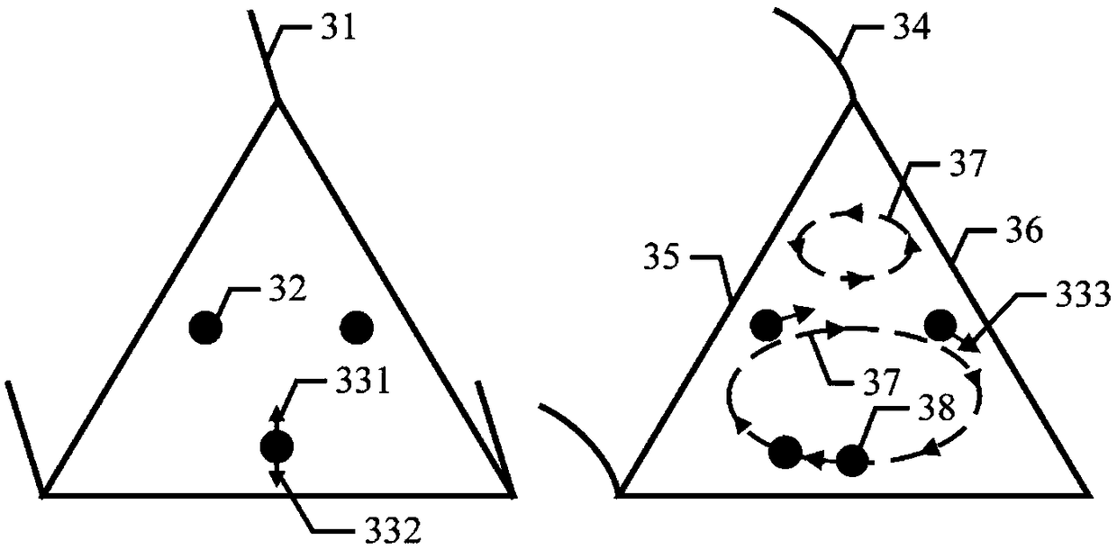
[0021] Figure 1-Figure 5 Middle: 11. Inlet Luer connector, 12. Microfluidic device main body, 13. Space microfluidic channel, 14. Inner outlet Luer connector, 15. Outer outlet Luer connector, 211. Sample inlet, 212. Inner sample outlet , 213, the sample outlet, 22a, the first liquid storage tank, 22b, the second liquid storage tank, 22c, the third liquid storage tank, 23, the sample introduction flow channel, 24, the connecting flow channel, 25, the special-shaped cross-sectional space spiral Flow channel, 26, sample outlet flow channel, 27, inner outlet flow channel, 28, outer outlet flow channel, 31, straight channel, 32, cell, 331, wall-induced inertial lift, 332, shear-induced inertial lift, 333, Dean drag force, 34, curved channel, 35, inner wall of curved channel, 36, outer wall of curved channel, 37, asymmetrical Dean flow, 38, unstable cell, 51, cancer cell...


PUM


Abstract

The invention provides a microfluidic device for precise cell control. The microfluidic device for precise cell control comprises an inlet end, a microfluidic device main body and an outlet end whichare sequentially connected, wherein the microfluidic device main body comprises a spatial spiral flow channel with a specially-shaped section; the two ends of the spatial spiral flow channel with thespecially-shaped section are communicated with the inlet end and the outlet end respectively; the cross section of the spatial spiral flow channel with the specially-shaped section is an isosceles triangle or a semicircle; the spatial spiral flow channel with the specially-shaped section adopts a spiral structure from top to bottom; the spiral structure has equal curvature radius; the inlet end comprises a sample inlet, a first liquid storage tank, a sample introducing flow channel and a connecting flow channel which are sequentially connected; the connecting flow channel is communicated withthe spatial spiral flow channel with specially-shaped section.

Description

technical field [0001] The invention relates to the field of microfluidic devices, in particular to a microfluidic device for precisely controlling cells. Background technique [0002] Due to its unique advantages such as low comprehensive cost, miniaturization of detection devices and instant diagnosis results, Point-of-Care Testing (POCT) is playing an important role in improving medical construction in resource-poor areas, responding to emergencies and disasters, and promoting home care diagnosis. and other fields have broad application prospects. The development of portable POCT instruments has become an emerging cross-research hotspot in the fields of life sciences and technical sciences. Relying on the advanced microstructure processing technology, microfluidics technology (Microfluidics) integrates the experimental processes involved in life science research, such as sampling, pretreatment and analysis and characterization, on a chip of a few square centimeters. It i...

Claims


Application Information

Patent Timeline
Patent Type & Authority Applications(China)
IPC IPC(8): C12M1/00
Inventor 唐文来李宗安朱莉娅杨继全
Owner 苏州中芯启恒科学仪器有限公司
Why Eureka
Try Eureka