Retaining wall water drainage system

A technology of drainage system and retaining wall, applied in the field of drainage system, can solve the problems of instability and damage of retaining wall, reducing the bearing capacity of foundation, etc.

Pending Publication Date: 2018-10-30
广州市设计院集团有限公司
View PDF0 Cites 2 Cited by
  • Summary
  • Abstract
  • Description
  • Claims
  • Application Information

AI Technical Summary

Problems solved by technology

In some projects, the accumulated water behind the retaining wall will even seep into the foundation below the retaining wall, reducing the bearing capacity of the foundation and causing the retaining wall to become unstable and damaged.

Method used


Image

  • Retaining wall water drainage system
  • Retaining wall water drainage system
  • Retaining wall water drainage system

Examples


Embodiment Construction

[0020] In order to make the above objects, features and advantages of the present invention more comprehensible, specific implementations of the present invention will be described in detail below in conjunction with the accompanying drawings. In the following description, numerous specific details are set forth in order to provide a thorough understanding of the present invention. However, the present invention can be implemented in many other ways different from those described here, and those skilled in the art can make similar improvements without departing from the connotation of the present invention, so the present invention is not limited by the specific embodiments disclosed below.

[0021] In the description of the present invention, it should be understood that the terms "first" and "second" are used for description purposes only, and cannot be interpreted as indicating or implying relative importance or implicitly indicating the quantity of indicated technical featu...


PUM


Abstract

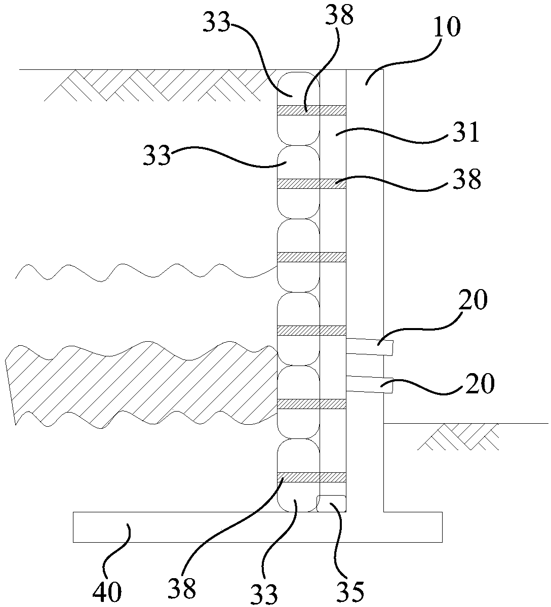
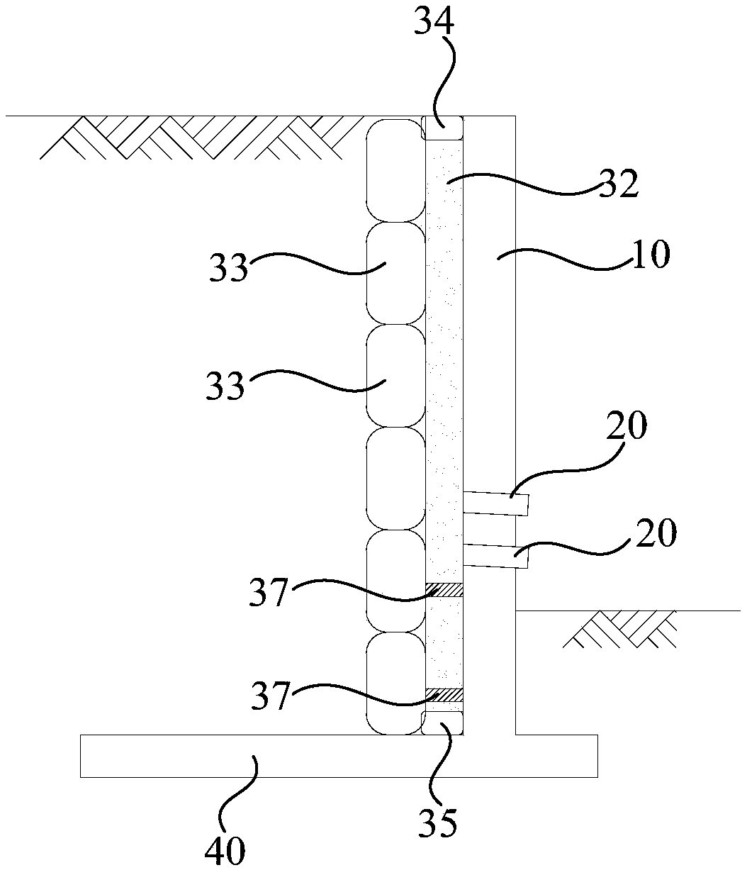
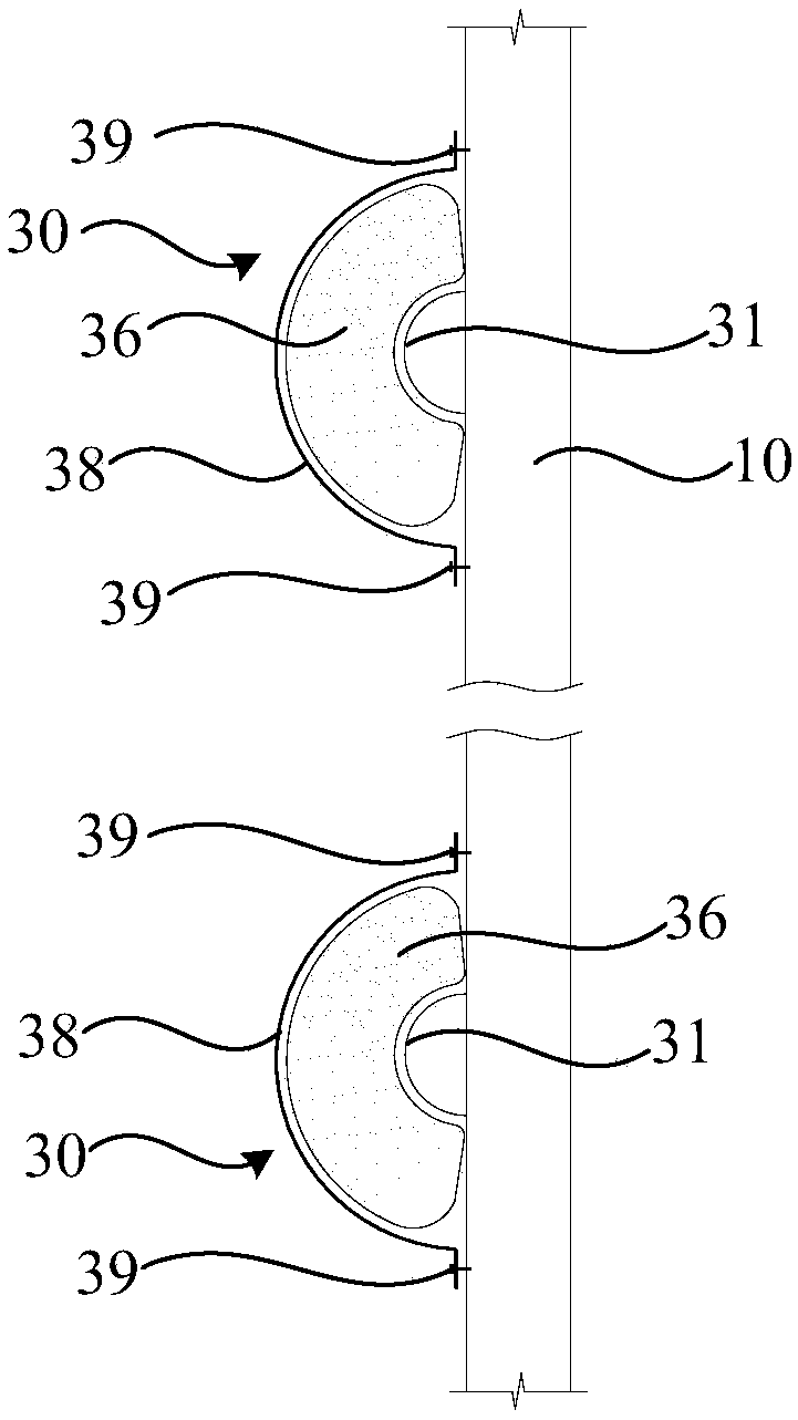
The invention relates to a retaining wall water drainage system. The system comprises a retaining wall, water drainage pipes and a vertical inverse filtering water drainage body; water drainage holesare formed in the bottom of the retaining wall, the water drainage holes penetrate to the other side wall of the bottom of the retaining wall from one side wall of the bottom of the retaining wall, the water drainage pipes are arranged on the water drainage holes, the vertical inverse filtering water drainage body is fixedly arranged on the side wall, facing the soil behind wall, of the retainingwall, the vertical inverse filtering water drainage body vertically and downwards extends to the bottom of the retaining wall from the top of the retaining wall, and the vertical inverse filtering water drainage body communicates with the water drainage holes; according to the retaining wall water drainage system, after the retaining wall is completed for a certain time, even if the soil behind the wall is sunken, the vertical inverse filtering water drainage body makes direct contact with the soil, within the different depth ranges, behind the retaining wall all the time, soil on different depths is collected to the vertical inverse filtering water drainage body in a diving manner, the vertical inverse filtering water drainage body drains the water outwards through the water drainage pipes, the water accumulation behind the retaining wall can be avoided, the retaining wall is kept in the long-term normal work all the time under the light load condition, and the service life of the retaining wall is prolonged as much as possible.

Description

technical field [0001] The invention relates to a drainage system, in particular to a retaining wall drainage system. Background technique [0002] It is difficult to compact the fill soil behind the retaining wall to a relatively high strength. After a certain period of time after the completion of the retaining wall, the fill soil behind the retaining wall begins to sink, and the filter bag on the side wall behind the retaining wall will sink accordingly. Sinking, causing the reverse filter bag to separate from the drain pipe, so that soil particles enter the drain pipe along the water to block the drain pipe, which will cause serious water accumulation behind the retaining wall. The accumulation of water behind the retaining wall will cause the wall to bear additional hydrostatic pressure or the expansion force of the clay filling after soaking in water, which will shorten the service life of the retaining wall. In some projects, the accumulated water behind the retainin...

Claims


Application Information

Patent Timeline
Patent Type & Authority Applications(China)
IPC IPC(8): E02D29/02E02D19/10
CPCE02D29/02E02D19/10
Inventor 黄俊光林祖锴罗永建
Owner 广州市设计院集团有限公司
Why Eureka
Try Eureka