
An energy-saving building ice room

A technology for private rooms and construction, applied in construction, building types, small buildings, etc., can solve the problems of laborious, difficult construction, poor thermal insulation effect, etc., to achieve easy reception of sunlight, easy random placement, safe and reliable fixation Effect

Inactive Publication Date: 2020-06-09
NANJING LISHUI HIGH-TECH VENTURE CAPITAL MANAGEMENT CO LTD
View PDF10 Cites 0 Cited by
  • Summary
  • Abstract
  • Description
  • Claims
  • Application Information

AI Technical Summary

Problems solved by technology

[0002] In the field of construction, green, energy-saving and environmental protection are the mainstream direction of construction, especially in remote cold areas, the construction is difficult, the cost is high, and it is not suitable for long-term residence. Currently, the buildings used for temporary residence in severe cold areas The equipment has the following defects: 1. Simple steel structure construction, which requires reinforcement of the construction foundation, which requires a large number of auxiliary machines. At the same time, when migration is required, auxiliary machines are required to dismantle and transfer, which is laborious and laborious. 2. 1. The heat preservation effect is poor, and the severe cold is lower than the large temperature difference between day and night. To increase the indoor temperature, it is necessary to add heating equipment for heating and increase equipment investment. 3. In a stormy weather environment, strong storms can easily penetrate the protective cover of the steel structure, so The indoor temperature cannot be effectively kept warm, so the present invention provides an energy-saving building ice room

Method used


Image

  • An energy-saving building ice room
  • An energy-saving building ice room
  • An energy-saving building ice room

Examples


Embodiment approach

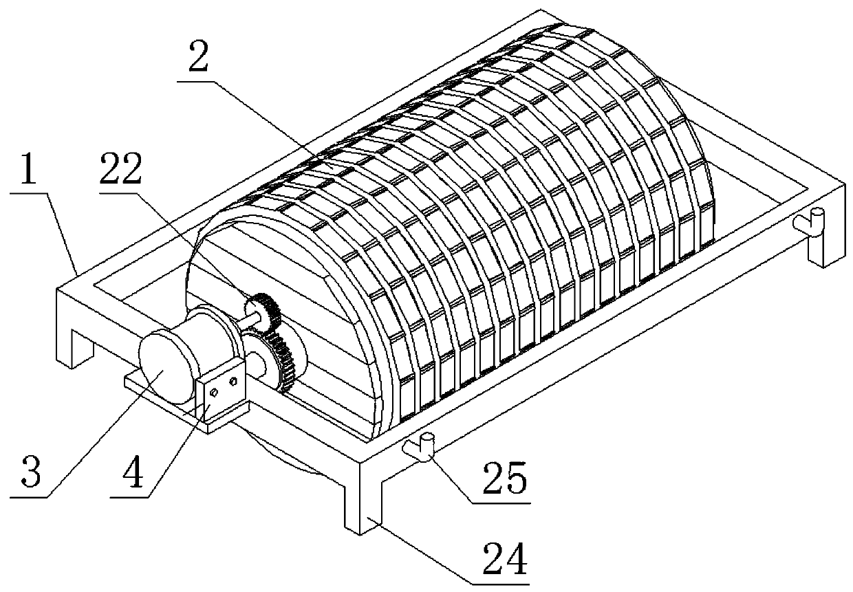
[0028] As a preferred embodiment of the present invention, the outer surfaces of the left ice pack plate 14 , the right ice pack plate 15 and the arc ice pack plate 16 are all provided with square ice cubes.

[0029] As a preferred embodiment of the present invention, the left light-transmitting plate 17 , the right light-transmitting plate 18 and the semicircular light-transmitting plate 19 are provided with ventilation holes.

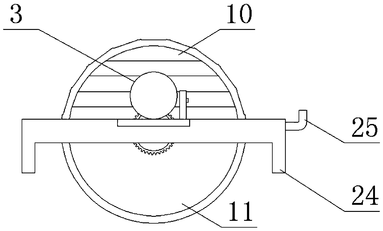
[0030] As a preferred embodiment of the present invention, the bottoms of the left crossbeam 5 and the right crossbeam 6 are provided with supporting feet 24 , and traction hooks 25 are arranged on the supporting feet 24 .

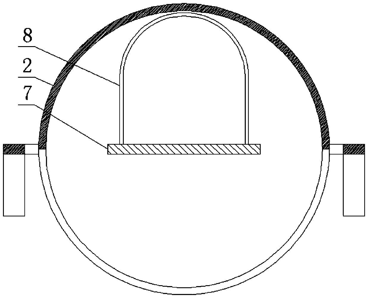
[0031] As a preferred embodiment of the present invention, the double-layer see-through CO 2 The protective cover 8 is provided with an injection hole.

[0032] As a preferred embodiment of the present invention, the gap between the outer side of the platform board 7 and the energy-saving protection combination 2 is 1-3 cm.

[0...


PUM


Abstract

The invention discloses an energy-saving type building ice bag room. The building ice bag room comprises a supporting base frame, an energy-saving protecting combination, a driving motor and a controlmachine set, wherein a left crossbeam, a right cross beam and a platform board are arranged on the supporting base frame, a double-layer transparent CO2 protecting cover is arranged on the platform board, a left revolving shaft and a right revolving shaft are arranged on two sides of the platform board, the platform board is connected with the left cross beam through the left revolving shaft, andthe platform board is connected with the right cross beam through the right revolving shaft; and the energy-saving protecting combination comprises a half-arc ice bag cover, a half-arc venting light-transmitting cover, a left revolving driving sleeve and a right fixing sleeve. By utilizing a 'greenhouse effect' principle, a through layer of the ice bag room is directly illuminated by sunshine inthe daytime, the indoor temperature is increased by virtue of the double-layer transparent CO2 protecting cover, and an inner room is covered with a half-arc ice layer of the ice bag room at night, sothat the wind-shielding and cold-insulation effects are achieved; and meanwhile, heat is dissipated into the room through the double-layer transparent CO2 protecting cover, so that the indoor temperature is increased.

Description

technical field [0001] The invention relates to the technical field of ice rooms, in particular to an energy-saving architectural ice room. Background technique [0002] In the field of construction, green, energy-saving and environmental protection are the mainstream direction of construction, especially in remote cold areas, the construction is difficult, the cost is high, and it is not suitable for long-term residence. Currently, the buildings used for temporary residence in severe cold areas The equipment has the following defects: 1. Simple steel structure construction, which requires reinforcement of the construction foundation, which requires a large number of auxiliary machines. At the same time, when migration is required, auxiliary machines are required to dismantle and transfer, which is laborious and laborious. 2. 1. The heat preservation effect is poor, and the severe cold is lower than the large temperature difference between day and night. To increase the indo...

Claims


Application Information

Patent Timeline
Patent Type & Authority Patents(China)
IPC IPC(8): E04H1/12E04B1/346E04B1/74E04B1/35
CPCE04B1/346E04B1/35E04B1/74E04H1/1205Y02A30/00
Inventor 朱静轩
Owner NANJING LISHUI HIGH-TECH VENTURE CAPITAL MANAGEMENT CO LTD
Learn More