
Heat-insulating and dustproof nail shooting device

A nail shooter and dust-proof technology, applied in nailing tools, U-shaped nailing tools, manufacturing tools, etc., can solve problems such as potential safety hazards, self-explosion of nail shooting bullets, and increased manufacturing costs

Pending Publication Date: 2018-11-02
YIBIN NANXI KECHENG ELECTROMECHANICAL FACTORY
View PDF0 Cites 3 Cited by
  • Summary
  • Abstract
  • Description
  • Claims
  • Application Information

AI Technical Summary

Problems solved by technology

[0007] However, the above method cannot be realized under the existing structural form, because the front end of the heat insulating sleeve is pressed tightly by the dust cover, and the inside has steps to limit the position, that is to say, the heat insulating sleeve is always covered outside the nail pipe, and more It is important that the axial length of the heat shield is greater than the axial length of the nail tube, so that there is no room for the tool to bite the nail tube
The length of the heat insulation sleeve is designed according to the size of the human hand and cannot be shortened; it is also unrealistic to artificially increase the length of the nail tube
[0008] 2. The heat in the space of the heat insulation sleeve cannot be effectively dissipated, which makes the internal temperature rise, which may cause the self-explosion of the nail bullet, forming a safety hazard
[0009] 3. The outer processing steps of the sound-absorbing sleeve increase the process and increase the manufacturing cost

Method used


Image

  • Heat-insulating and dustproof nail shooting device
  • Heat-insulating and dustproof nail shooting device
  • Heat-insulating and dustproof nail shooting device

Examples


Embodiment 1

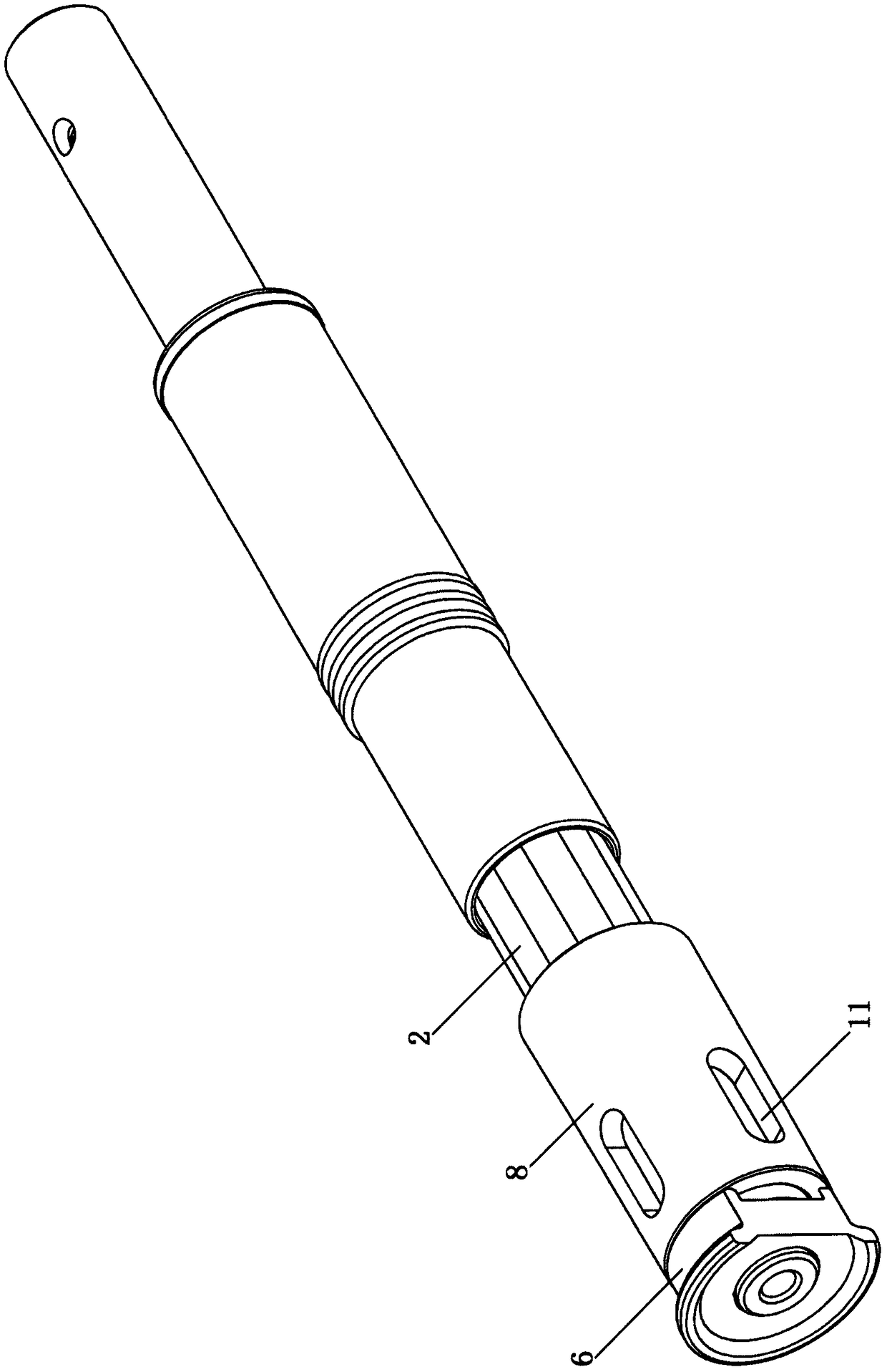
[0024] In the figure: 1 is the nail tube, 2 is the movable sleeve, 3 is the thread, 4 is the silencer sleeve, 5 is the thread, 6 is the dust cover, 7 is the thread, 8 is the heat insulation sleeve, 9 is the step A; 10 It is step B.

[0025] When in normal use, the dust cover 6 prevents the dust from falling. After firing, hold the non-hot heat insulation sleeve 8 and pull it back. The step B10 will force the movable cover 2 to move backward through the step A9 to realize the retreat. shell.

[0026] The action structure of the nail shooter, such as loading, firing, ejecting, and resetting, belongs to the conventional technology, and has been described in detail in the applicant's previous patent, so the description will not be repeated here.

[0027] When the screw thread 7 is damaged, a torsion force is applied between the movable sleeve 2 and the dust cover 6 to separate the two. Since the heat insulating sleeve 8 does not completely cover the movable sleeve 2 and the scre...

Embodiment 2

[0031] Heat dissipation through-holes 11 are arranged on the heat-insulating cover, which can dissipate internal heat, lower the temperature, and reduce potential safety hazards.


PUM


Abstract

The invention relates to a heat-insulating and dustproof nail shooting device. The device comprises a nail pipe, the rear end of the nail pipe is in threaded connection with a movable sleeve, a noisereduction sleeve is in threaded connection with the nail pipe, the front end of the nail pipe is in threaded connection with a dustproof cover, a heat insulation sleeve is covered with the noise reduction sleeve, and the front end of the heat insulation sleeve is in contact with the dustproof cover; and the heat-insulating and dustproof nail shooting device is characterized in that a movable sleeve major diameter is larger than the noise reduction sleeve major diameter, and a step A is formed; a step B is arranged in the dustproof cover, and force transmission can be achieved between the stepA and the step B. The heat-insulating and dustproof nail shooting device has the beneficial effects that on the premise that the working mode and effect of original equipment are not changed, a stressrelation is ingeniously changed, the heat insulation sleeve and inner assemblies ( such as the nail pipe and the noise reduction sleeve ) are enabled not to be limited in relation, and then a damagedpart can be smoothly taken out, unscrewed, cleared and repaired, so that the actual problem existing at the present stage is solved.

Description

technical field [0001] The invention discloses a nail shooting device. Background technique [0002] With the development of the nailer technology, the various advantages of the axial nailer make its application more and more extensive. [0003] There are two problems that the axial nailer must solve: one is to avoid burns when the shell is manually ejected, and the other is to prevent the dust on the top surface from falling into the eyes of the operator and the noise caused by the explosion during the nailing action. The relatively common technical means adopted at this stage are to install heat insulation sleeves and dust covers. Concrete installation method is to be screwed with nail pipe before movable sleeve, and nail pipe and sound-absorbing sleeve threaded connection; Nail pipe front end is connected dust cover (compression nut) by thread. The sound-absorbing sleeve is covered with a heat-insulating sleeve; there is a step (inclined platform) between the outer circ...

Claims


Application Information

Patent Timeline
Patent Type & Authority Applications(China)
IPC IPC(8): B25C1/10B25C1/18B25C7/00
CPCB25C1/10B25C1/18B25C7/00
Inventor 方福政方鹤周建
Owner YIBIN NANXI KECHENG ELECTROMECHANICAL FACTORY
Learn More