Supercharge Your Innovation With Domain-Expert AI Agents!

High temperature flue gas cooling device

A cooling device and high-temperature flue gas technology, applied in the field of flue gas treatment, can solve problems such as poor cooling effect of high-temperature flue gas, and achieve the effects of good condensation effect, low energy consumption and simple structure

Active Publication Date: 2019-12-31
GUIZHOU HUANKE ENVIRONMENT ECOLOGICAL RES & DEV CO LTD
View PDF7 Cites 0 Cited by
  • Summary
  • Abstract
  • Description
  • Claims
  • Application Information

AI Technical Summary

Problems solved by technology

[0004] The purpose of the present invention is to provide a high-temperature flue gas cooling device to solve the problem of poor cooling effect of high-temperature flue gas

Method used


Image

  • High temperature flue gas cooling device

Examples


Embodiment Construction

[0027] The present invention will be described in further detail below by means of specific embodiments:

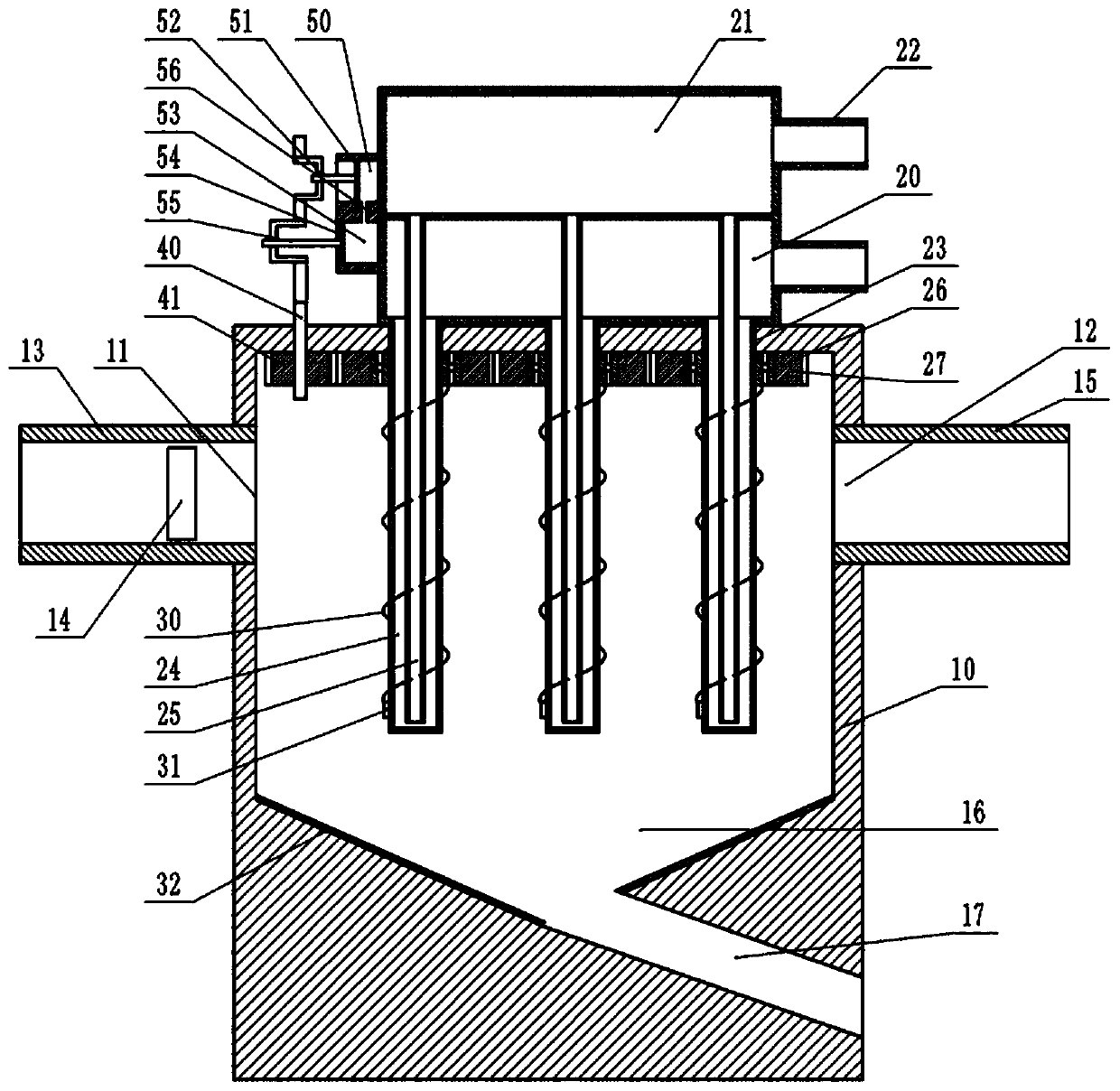
[0028] The reference signs in the drawings of the description include: box body 10, air inlet 11, air outlet 12, air inlet pipe 13, axial flow fan 14, air outlet pipe 15, collection chamber 16, discharge pipe 17, cold water tank 20, Hot water tank 21, water exchange pipe 22, condensation pipe 23, outer pipe 24, inner pipe 25, bearing 26, first gear 27, scraper rod 30, magnetic block 31, electromagnet 32, pole 40, second gear 41 , the first air box 53, the first piston 54, the first plug rod 55, the second air box 50, the second piston 51, the second plug rod 52, and the vent pipe 56.

[0029] like figure 1 As shown, the high-temperature flue gas cooling device includes a box body 10, the box body 10 is provided with an air inlet 11 and an air outlet 12, the air inlet 11 is provided with an air inlet pipe 13, the air outlet 12 is provided with an air outlet pipe 15, and t...


PUM


Abstract

The invention belongs to the technical field of smoke treatment and particularly discloses a high-temperature smoke cooling device comprising a box provided with an air inlet and an air outlet. A collection cavity is formed in the lower portion in the box. A discharge pipe communicating with the collection cavity is arranged at the lower end of the box. A cold water tank is arranged at the upper end of the box. A hot water tank is arranged at the upper end of the cold water tank. The hot water tank and the cold water tank each communicate with a water change pipeline. A plurality of condensingpipes are arranged in the box and comprise outer pipes communicating with the cold water tank, and inner pipes communicating with the hot water tank. The lower ends of the inner pipes communicate with the outer pipes. Compared with the prior art, the high-temperature smoke cooling device is simple in structure, small in size, low in energy consumption and capable of continuously condensing high-temperature smoke and ensuring a good condensing effect.

Description

technical field [0001] The invention belongs to the technical field of flue gas treatment, and specifically discloses a high-temperature flue gas cooling device. Background technique [0002] At present, in many industries such as metallurgy, building materials, electric power, and chemical industry, a large amount of flue gas containing dust will be generated. In order to protect the environment from pollution, such flue gas cannot be directly discharged into the environment, and dust removal treatment is required. At present, most of the flue gas dust removal adopts dry bag type dust removal, that is, the cloth bag is used to filter the flue gas to achieve the dust removal effect. [0003] Dry bag type dust removal requires that the flue gas temperature be controlled above the dew point temperature to ensure no condensation, and the flue gas temperature must be controlled within the temperature range allowed by the filter bag. However, the flue gas that needs to be treate...

Claims


Application Information

Patent Timeline
Patent Type & Authority Patents(China)
IPC IPC(8): F28D21/00
CPCF28D21/0014
Inventor 赵明伦袁志勇张朝友袁世国
Owner GUIZHOU HUANKE ENVIRONMENT ECOLOGICAL RES & DEV CO LTD
Features
  • R&D
  • Intellectual Property
  • Life Sciences
  • Materials
  • Tech Scout
  • Unparalleled Data Quality
  • Higher Quality Content
  • 60% Fewer Hallucinations
Learn More