H-shaped finned tube with radially-formed slits on surface

A finned tube and radial technology, applied in the field of H-shaped finned tubes with radial slits on the surface, can solve the problems of low heat transfer efficiency and heat transfer deterioration, achieve long life, save steel consumption, and avoid heat transfer area Effect

Inactive Publication Date: 2018-11-02
XI AN JIAOTONG UNIV
View PDF4 Cites 2 Cited by
  • Summary
  • Abstract
  • Description
  • Claims
  • Application Information

AI Technical Summary

Problems solved by technology

[0006] Traditional H-shaped fins have their inherent disadvantages. For example, the smooth surface of the fins does not form disturbances, which

Method used


Image

  • H-shaped finned tube with radially-formed slits on surface
  • H-shaped finned tube with radially-formed slits on surface
  • H-shaped finned tube with radially-formed slits on surface

Examples


Embodiment Construction

[0032] The present invention will be described in more detail below in conjunction with the accompanying drawings and specific embodiments. The following examples are helpful for those skilled in the art to better understand the present invention, but do not limit the present invention in any form. And it should be pointed out that for those skilled in the art of research, improvements can be made on the basis of the concept of the present invention, which all belong to the protection scope of the present invention.

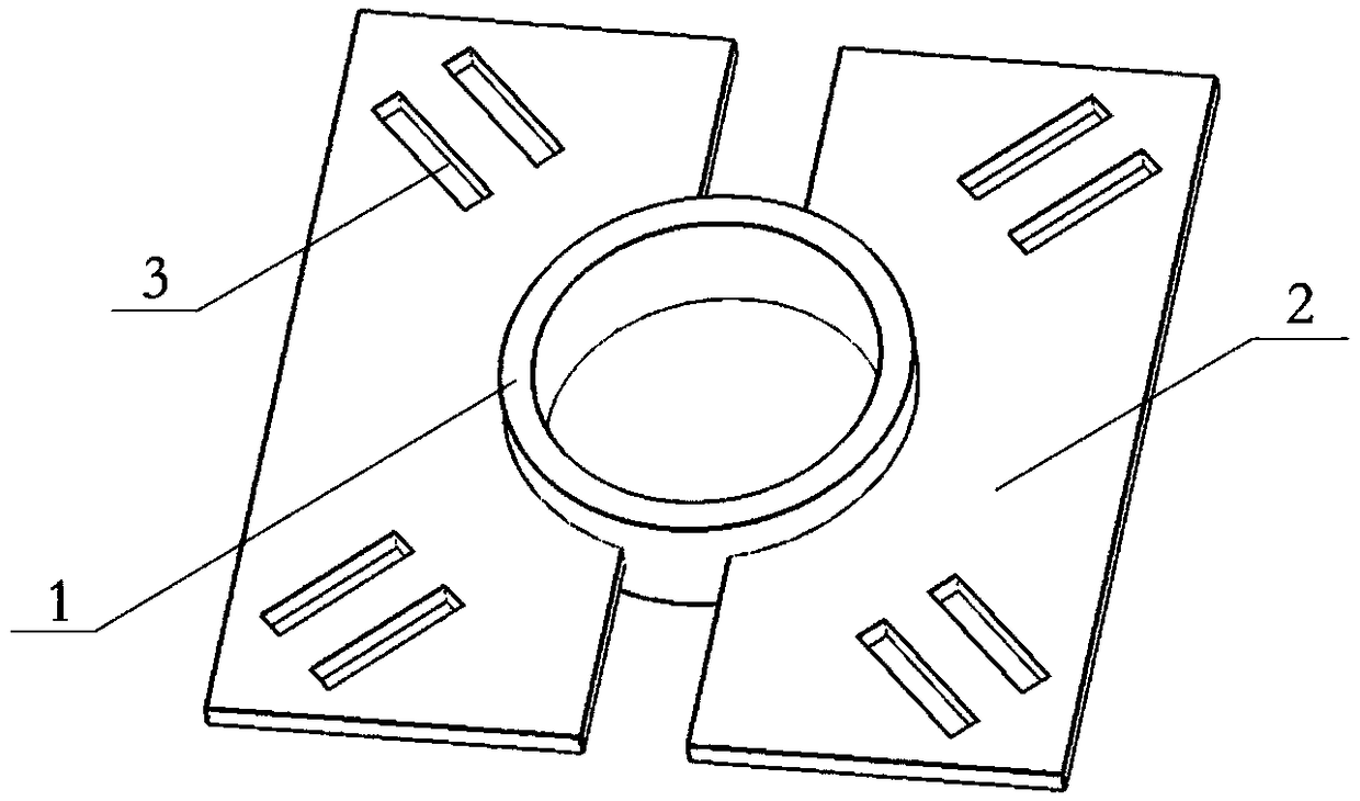
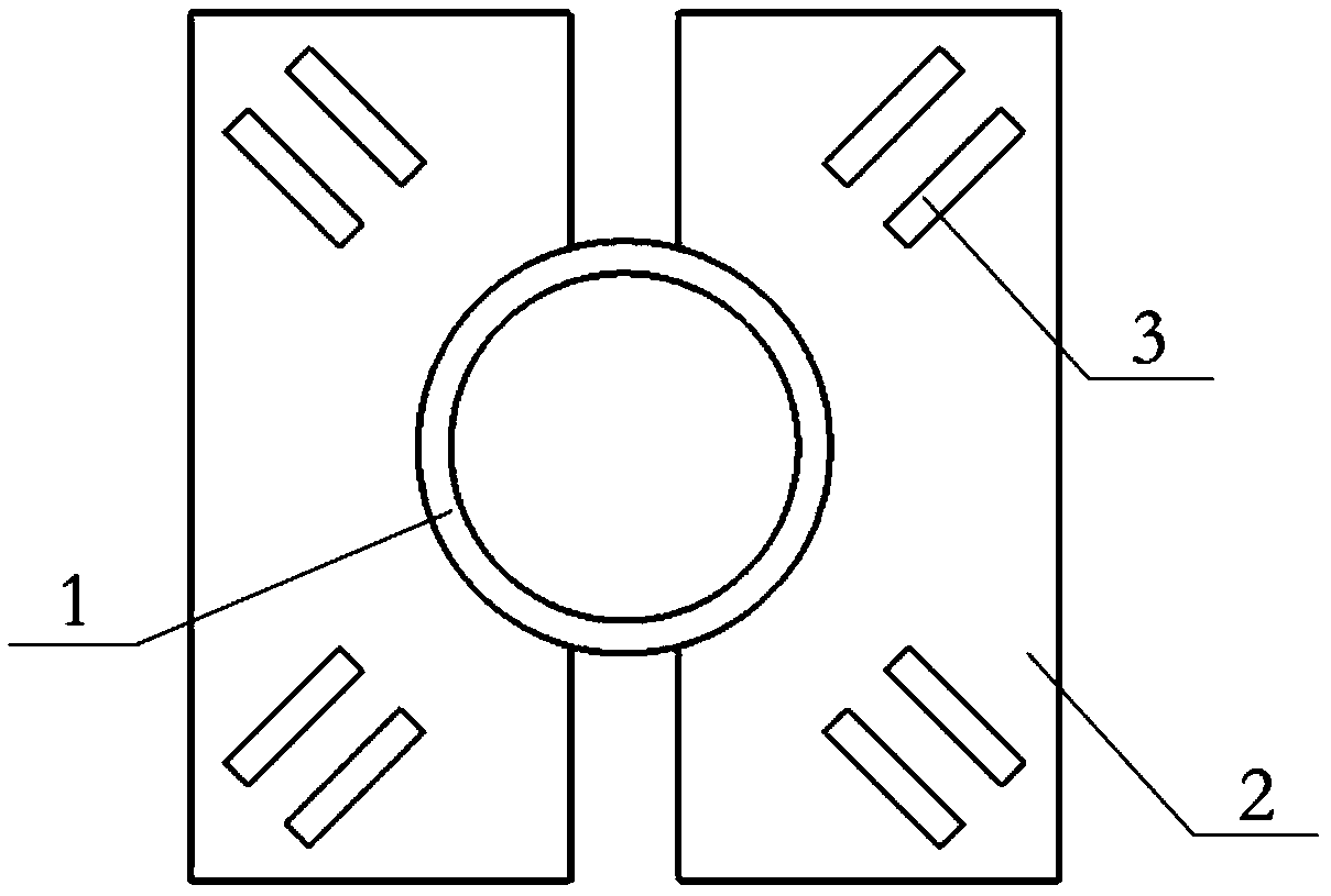
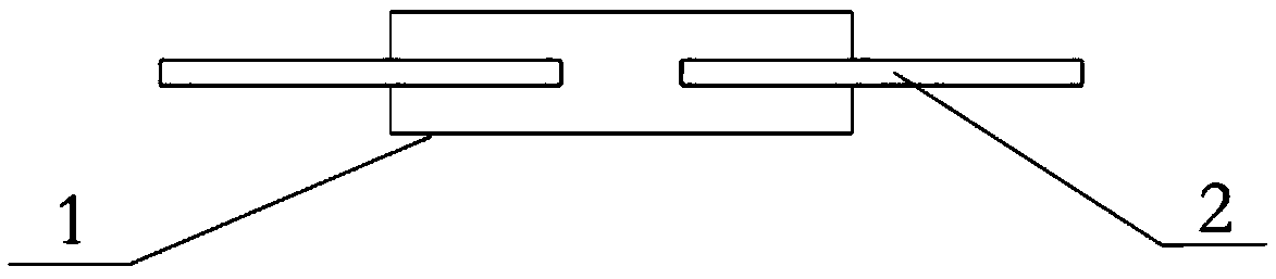
[0033] Such as figure 1 , figure 2 with image 3 As shown, a H-shaped finned tube with radial slits on the surface includes a base tube 1 and a plurality of fin groups 2 arranged axially along the base tube 1 and set on both sides of the outer wall of the base tube; each fin group 2 is composed of two fins, the fins are rectangular, symmetrically connected to the outer wall of the base tube 1 through the groove on the side of the base tube, the two fins are l...


PUM


Abstract

The invention discloses an H-shaped finned tube with radially-formed slits on the surface. The H-shaped finned tube comprises a base tube and a plurality of fin sets which sleeve the two sides of theouter wall of the base tube correspondingly and are arranged in the axial direction of the base tube; each fin set is composed of two fins, the fins for each fin set are rectangular and are connectedwith the outer wall of the base tube in a symmetrical mode through side grooves of the fins arranged on the sides, next to the base tube, of the fins, the two fins for each fin set are located on thesame horizontal plane perpendicular to the axial direction of the base tube, a certain gap is formed between the two fins for each fin set, and the plurality of slits are formed in the surfaces of thefins; and the included angles between the slits and the incoming flow direction range from 40 degrees to 50 degrees, and the slits are symmetrically arranged on the two sides of the connecting linesbetween the center of the base tube and the four corners of the fins. According to the H-shaped finned tube, disturbance can be well carried out through the slits on the surfaces on the exterior fluidso as to damage the boundary layer to strengthen the heat transfer; then, the directions of the slits hardly affect the heat conduction inside the finned tube, and therefore, the fin efficiency cannot be reduced; and again, the directions of the slits and the flowing direction can reduce the flowing resistance which is increased due to the damage of the boundary layer as much as possible while the disturbance is formed and the damage boundary layer is damaged, moreover, the flowing friction area is reduced, and due to the two factors, the flowing resistance of the fined tube is integrally reduced.

Description

technical field [0001] The invention belongs to the technical field of heat exchangers for flue gas waste heat utilization, and is suitable for heat exchange equipment and heating equipment in industries such as energy, power, refrigeration, chemical industry, smelting, petroleum, etc., and specifically relates to an H-shaped fin with radial slits on the surface Tube. Background technique [0002] With the sustained and rapid development of my country's economy, the problem of energy supply shortage has become increasingly prominent, and energy conservation, emission reduction and consumption reduction have become the inevitable requirements of my country's economic and social development. As an important part of power, petroleum, chemical, refrigeration, metallurgy, and even aviation, rocket and other industrial processes, heat exchangers are of great significance for their safe and efficient operation. In various heat exchange equipment, increasing the heat exchange area ...

Claims


Application Information

Patent Timeline
IPC IPC(8): F28F1/30F28F13/02F28F13/06F28F19/00F22D1/08
CPCF28F1/30F22D1/08F28F13/02F28F13/06F28F19/00F28F2215/08F28F2250/10
Inventor 王皓皓严俊杰刘明马其然刘继平
Owner XI AN JIAOTONG UNIV
Why Eureka
Try Eureka