Developer conveying mechanism, and developing device and image forming apparatus therewith

A conveying mechanism and developer technology, applied to the electric recording process using charge patterns, equipment for electric recording processes using charge patterns, and electrography, etc. It can solve the problems of reduced sealing effect, leakage of developer outlets, and gate action. Achieve sufficient sealing performance, smooth operation, and reduced sliding load by eliminating problems such as defects

Inactive Publication Date: 2018-11-02
KYOCERA DOCUMENT SOLUTIONS INC
View PDF4 Cites 1 Cited by
  • Summary
  • Abstract
  • Description
  • Claims
  • Application Information

AI Technical Summary

Problems solved by technology

However, there is a problem that if the sliding load between the gate and the sealing member becomes large, the gate may malfunction and the discharge port cannot be completely closed, and the developer may leak from the discharge port.
On the other hand, if the sliding area between the sealing member and the gate is reduced, the sliding load will be reduced, but the sealing effect will also be reduced.

Method used


Image

  • Developer conveying mechanism, and developing device and image forming apparatus therewith
  • Developer conveying mechanism, and developing device and image forming apparatus therewith
  • Developer conveying mechanism, and developing device and image forming apparatus therewith

Examples


Embodiment Construction

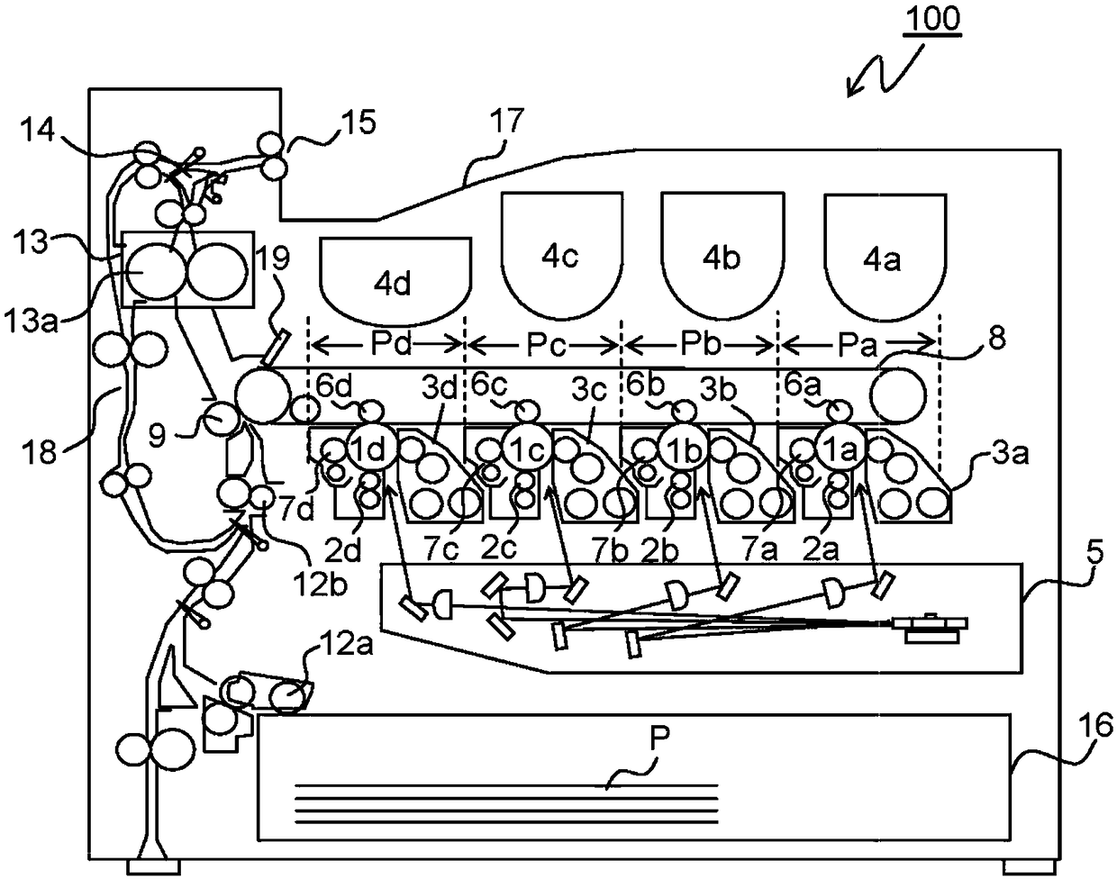
[0038] Hereinafter, embodiments of the present invention will be described with reference to the drawings. figure 1 It is a schematic sectional view of the image forming apparatus of the present invention, and a tandem color printer is shown here. In the main body of the color printer 100, the four image forming sections Pa, Pb, Pc, and Pd are viewed from the upstream side in the conveying direction ( figure 1 (middle is the right side) are configured in sequence. These image forming parts Pa to Pd are provided corresponding to images of different four colors (cyan, magenta, yellow, and black), and sequentially form cyan, magenta, yellow, and black through the processes of charging, exposure, development, and transfer, respectively. Yellow, and black images.

[0039] In these image forming sections Pa to Pd, photosensitive drums 1 a , 1 b , 1 c , and 1 d that carry visible images (toner images) of respective colors are arranged, respectively. Further, in figure 1 The inter...


PUM


Abstract

The invention provides a developer conveying mechanism, and a developing device and an image forming apparatus therewith. The developer conveying mechanism has a pipe-shaped conveyance passage, a shutter, a sealing member, and a biasing member. Through the pipe-shaped conveyance passage, developer is conveyed, and a discharge port is formed in a part of a side surface of the pipe-shaped conveyancepassage. The shutter is arranged to be slidable along the outer circumferential surface of the pipe-shaped conveyance passage, and opens and closes the discharge port. The sealing member is fixed tothe inner circumferential surface of the shutter. The biasing member biases the shutter in a direction in which the discharge port is closed. The sealing member has a frame-shaped contact portion making contact with the pipe-shaped conveyance passage, and a non-contact portion in the contact portion.

Description

technical field [0001] The present invention relates to a developer conveying mechanism used in image forming apparatuses such as copiers, printers, facsimile machines, and multifunction machines thereof, and more particularly to a mechanism for opening and closing a developer discharge port formed in a passage for conveying developer . Background technique [0002] Conventionally, among the developing devices of the two-component developing system, there has been proposed a developing device which replenishes a developer containing a carrier into a developing container in order to prevent a decrease in the charging application performance of the carrier, and is provided with a developer for discharging the excess developer. Discharge section. In this developing device, it is necessary to prevent damage caused by friction between components such as the developing roller during initial driving, and therefore the developing roller is previously filled with developer in an amo...

Claims


Application Information

Patent Timeline
IPC IPC(8): G03G15/08
CPCG03G15/0881G03G15/0886G03G15/0891G03G15/0893G03G15/0898
Inventor 辻浩文所义多贺
Owner KYOCERA DOCUMENT SOLUTIONS INC
Why Eureka
Try Eureka