
Vacuole computing method under podded propulsor deflection condition

A calculation method and thruster technology, applied in the directions of calculation, instrumentation, design optimization/simulation, etc., can solve the problems of increasing grid division time, loss of meaningful information, high requirements on grid quantity and quality, and achieve network saving. Grid division time, improve computing efficiency, high practical effect

Active Publication Date: 2018-11-02
NAVAL UNIV OF ENG PLA
View PDF3 Cites 3 Cited by
  • Summary
  • Abstract
  • Description
  • Claims
  • Application Information

AI Technical Summary

Problems solved by technology

The RNS method (Reynolds time averaging, a numerical simulation method for turbulent flow) and LES (large eddy simulation, a numerical simulation method for turbulent flow) have become the main methods, but RNS smooths out all the behavioral details of the pulsating motion through the average operation, and loses The pulsation item contains a large amount of meaningful information, and treats vortices of different scales equally without distinction, which is not realistic; the LES method can use detailed calculation of pulsation motion to obtain more flow field information, but due to The requirement for grid quantity and quality is too high, it consumes computing power and time, and is not adopted by most scholars
[0004] In terms of grid division, due to the unstructured grid’s poor calculation of viscosity and low grid filling rate, the same space needs to be filled with a large number of grids , increase the calculation time; at the same time, for the deflection problem, since the corresponding models are different under different deflection conditions during the steering process, the grid needs to be re-divided, which will greatly increase the time of grid division

Method used


Image

  • Vacuole computing method under podded propulsor deflection condition
  • Vacuole computing method under podded propulsor deflection condition
  • Vacuole computing method under podded propulsor deflection condition

Examples


Embodiment Construction

[0034] In order to make the purpose, technical solutions and advantages of the embodiments of the present invention clearer, the technical solutions of the present invention will be described below in conjunction with specific embodiments and accompanying drawings. The described embodiments are preferred solutions of the present invention, and Not all implementations. Based on the embodiments of the present invention, all other embodiments obtained by persons of ordinary skill in the art without making creative efforts belong to the protection scope of the present invention.

[0035] The specific purpose of the present invention is to provide a method for calculating the cavitation performance of different deflection angles of the pod propeller, through which the data processing speed and efficiency can be effectively improved, the difficulty of the calculation process and the demand for hardware can be reduced, and The calculation results are more in line with the actual situ...


PUM


Abstract

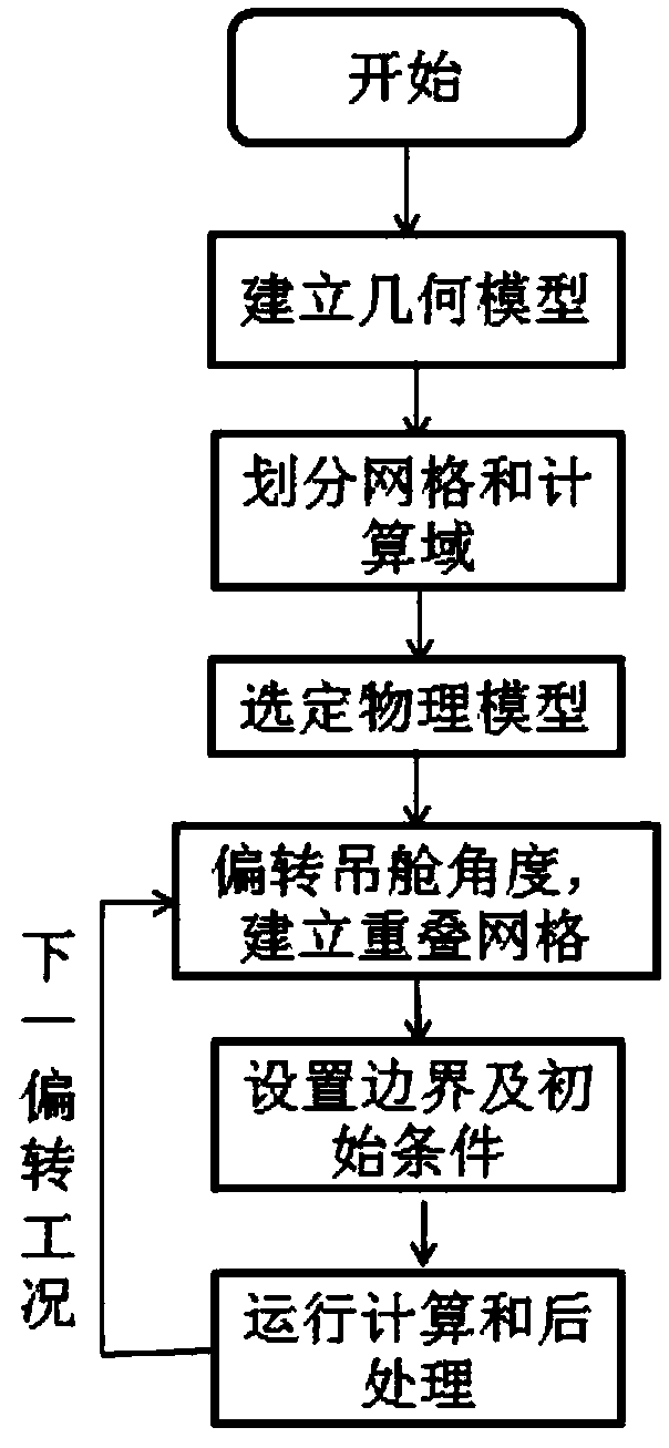
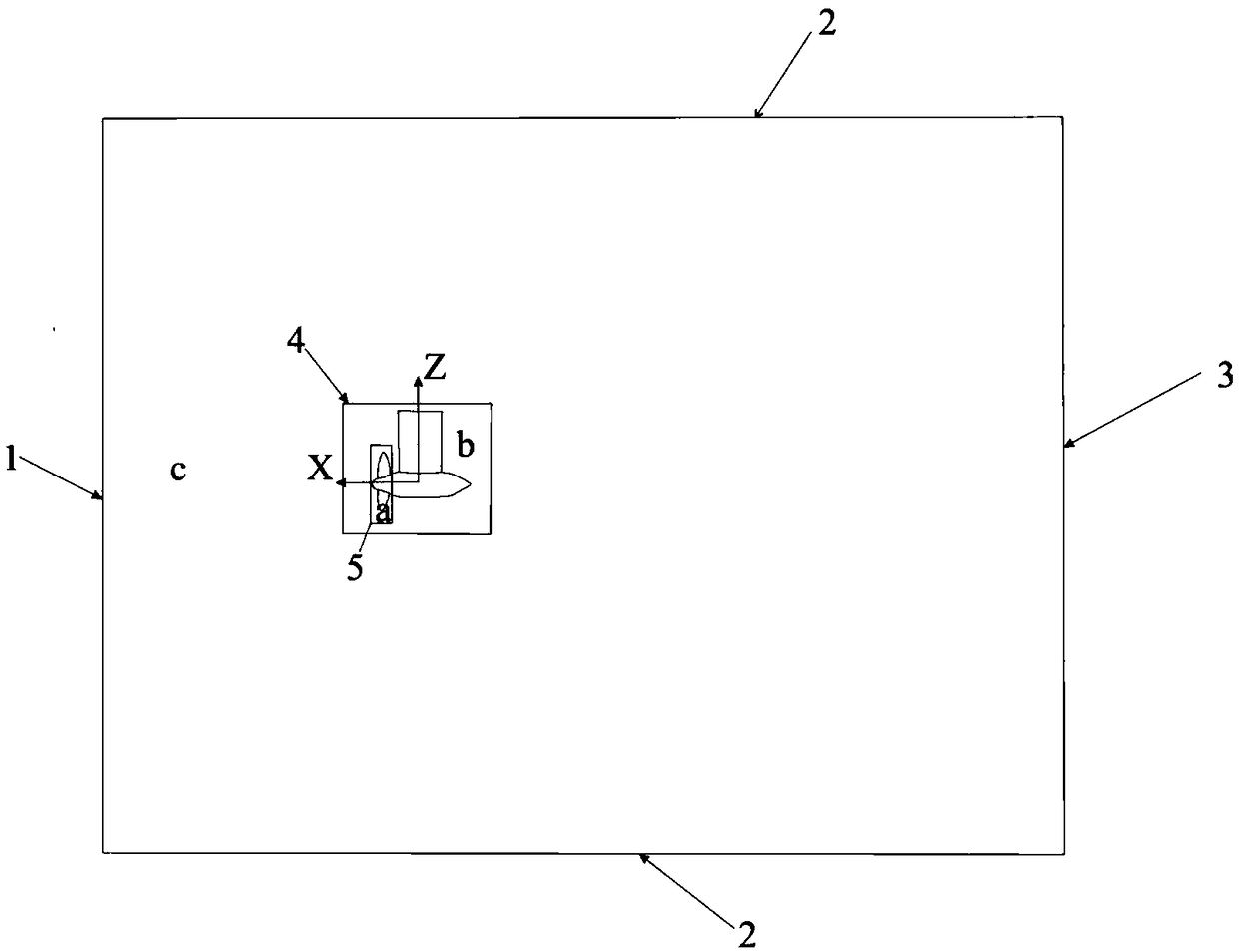
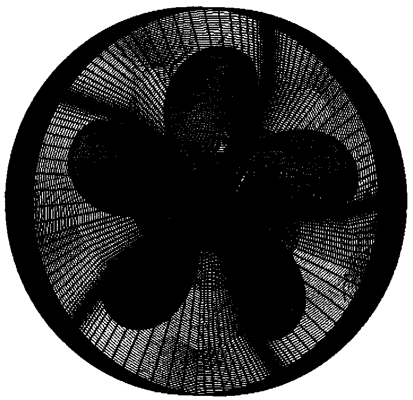
The invention provides a vacuole computing method under a podded propulsor deflection condition. The method comprises the steps that a three-dimensional model is established; computational domain fluid meshing is performed; a physical model is selected; boundary conditions and initial conditions are set according to a podded propulsor deflection angle; solver parameters are set; and grading computation is performed, wherein steady-state computation is adopted first, then unsteady-state computation is performed, and then outlet pressure is lowered step by step to an actual value. According to the method, the vacuole form of a pod propeller under the podded propulsor deflection condition is solved through CFD software; and by the adoption of full-structure meshes, turbulent dissipation solving is benefited, the quantity of the meshes is reduced, computing efficiency is improved, the vacuole form under the podded propulsor deflection condition is accurately simulated, and the consistencyis good compared with a test result.

Description

technical field [0001] The invention belongs to the technical field of thrusters, and in particular relates to a cavitation performance calculation method under the deflection working condition of a pod. Background technique [0002] When the ship propeller is running at high speed, when the negative pressure on the back of the blade is lower than the vaporization pressure of water, cavitation is very easy to occur, resulting in cavitation. The generation and collapse of the cavitation will erode the blades and reduce the propulsion efficiency of the propeller. At the same time, it will generate a huge induced pulsating pressure on the bottom of the ship, causing severe vibration at the tail of the ship. In recent years, pod propulsion has been widely used in various ships due to its good maneuverability. The pod propeller deflects during the steering process, which increases the load on the propeller blade, deteriorates the cavitation performance, and damages the propeller...

Claims


Application Information

Patent Timeline
IPC IPC(8): G06F17/50
CPCG06F30/15G06F30/20Y02T90/00
Inventor 李善成熊鹰黄政徐野袭鹏
Owner NAVAL UNIV OF ENG PLA
Learn More