Socket

A socket and socket hole technology, applied in the electrical field, can solve the problems of surface dust, dust or water droplets entering, causing harm, etc., and achieve the effect of preventing dust and dust and water from falling into

Inactive Publication Date: 2018-11-02
赵俊
View PDF0 Cites 0 Cited by
  • Summary
  • Abstract
  • Description
  • Claims
  • Application Information

AI Technical Summary

Problems solved by technology

[0002] The socket can be a switch socket fixed on the wall, or a mobile socket, but whether it is a switch socket or a mobile socket, after a period of use, the surface will become dusty, and dust or water droplets will Entering the inside of the socket will affect the use and even cause harm. Although there are switches on the market, when the plug is pulled out, the internal plastic baffle will prevent dust from falling in, but this design is actually useless. Because when there is dust, water droplets will fall in the socket hole, although it can prevent the dust and water droplets from contacting the conductors inside the socket at that time, when the plug is inserted, the dust or water droplets that fall in the socket hole will be brought in, which is still not enough. In addition, some sockets have more than one plug, and if some socket holes are not suitable, there will still be a possibility of harm

Method used


Image

  • Socket
  • Socket
  • Socket

Examples


Embodiment 1

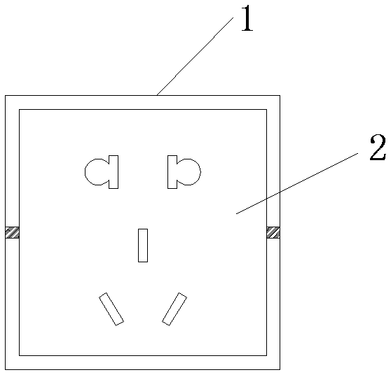
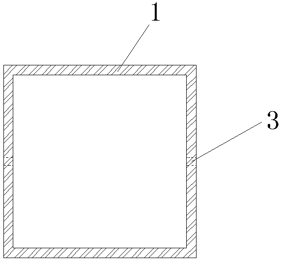
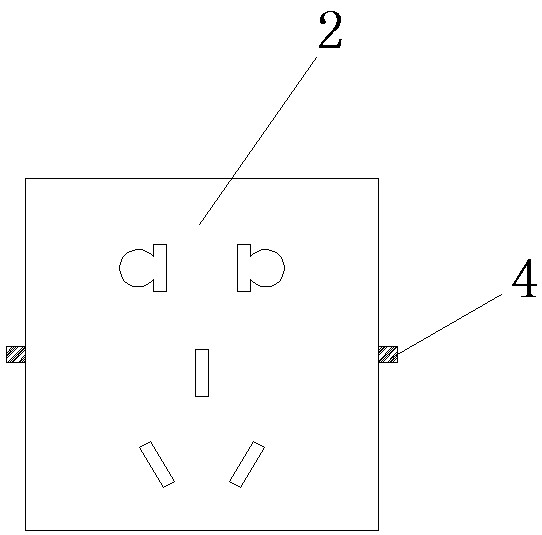
[0052] a socket such as figure 1 As shown, it includes the socket slot 1 and the socket body 2, the socket slot 1 and the socket body 2 are rotatably connected, and the socket slot 1 is a cube, such as Figure 4 As shown, the inner wall of socket groove 1 is provided with two relative shaft holes 3, and these two shaft holes 3 can be up and down, or left and right, as figure 2 In the schematic diagram shown, the shaft hole 3 is opened on the left and right, and the shaft hole 3 runs through the inner wall of the socket groove 1, image 3 Shown is a schematic diagram of the structure of the socket body 2. There are rotating shafts 4 on both sides of the socket body 2. The rotating shaft 4 is hollow. The rotating shaft hole 3 matches the rotating shaft 4. The setting of the hollow rotating shaft 4 can connect the wires. 15 passes through the hollow rotating shaft 4, and is electrically connected with the conductor in the socket hole, as Figure 15 As shown; when the plug need...

Embodiment 2

[0054] A socket, the same as Embodiment 1, the difference is that the socket groove 1 is hemispherical, and the socket body 2 is circular, such as Figure 5-8 shown.

Embodiment 3

[0056] Such as Figure 5-6As shown, the socket body 2 is provided with a card slot 6 around, and the dust-proof sheet 5 is arranged in the card slot 6, and the dust-proof sheet 5 is provided with a socket hole. When in use, connect the socket hole on the dust-proof sheet 5 with the socket body The socket holes on 2 correspond to each other, and then the plug can be plugged in. If the plug is not needed, the dust-proof sheet 5 can be rotated, so that dust is difficult to enter the socket; The design of 5 is not only suitable for the rotary connection between the socket slot 1 and the socket body 2, but also for the fixed connection commonly existing in the market, or other designs. In addition, the dust-proof sheet 5 can be replaced .


PUM


Abstract

The invention discloses a socket, and belongs to the field of electricity. The socket comprises a socket groove and a socket body, wherein the socket groove is rotatably connected with the socket body, and socket holes are rotated to the socket groove by rotation when the socket is not used so as to prevent dust dropping. A dustproof thin plate is arranged on the socket body, the socket holes areformed in the dustproof thin plate, and dust and water can be prevented from falling by rotating the dustproof thin plate when the socket is not used; by arrangement of a curtain box, dust can be prevented from falling, and the other socket holes which are not used can be shielded by a curtain in the curtain box when more than one plugs are inserted; and a maintenance door is arranged on a back surface of the socket body, maintenance can be performed by the maintenance door when the socket is encountered with problem and is needed to be maintained, and dust also can be cleaned out by the maintenance door when the dust falls into the socket.

Description

technical field [0001] The invention relates to the field of electricity, and more specifically, to a socket. Background technique [0002] The socket can be a switch socket fixed on the wall, or a mobile socket, but whether it is a switch socket or a mobile socket, after a period of use, the surface will become dusty, and dust or water droplets will Entering the inside of the socket will affect the use and even cause harm. Although there are switches on the market, when the plug is pulled out, the internal plastic baffle will prevent dust from falling in, but this design is actually useless. Because when there is dust, water droplets will fall in the socket hole, although it can prevent the dust and water droplets from contacting the conductors inside the socket at that time, when the plug is inserted, the dust or water droplets that fall in the socket hole will be brought in, which is still not enough. In addition, some sockets have more than one plug, and if some socket ...

Claims


Application Information

Patent Timeline
Patent Type & Authority Applications(China)
IPC IPC(8): H01R13/502H01R13/52H01R13/70H01R27/00H01R35/00
CPCH01R13/502H01R13/52H01R13/5213H01R13/70H01R27/00H01R35/00
Inventor 赵俊段旭尧
Owner 赵俊
Why Eureka
Try Eureka