Pilot frequency transmission and receiving methods and devices

A transmission method and pilot reception technology, applied in the field of communication, can solve the problems of reduced effective spectrum utilization rate of the system, difficulty in meeting service delay requirements, and large delay

Active Publication Date: 2018-11-02
DATANG MOBILE COMM EQUIP CO LTD
View PDF5 Cites 1 Cited by
  • Summary
  • Abstract
  • Description
  • Claims
  • Application Information

AI Technical Summary

Problems solved by technology

[0005] use figure 1 As shown in the pilot pattern, in order to obtain the frequency domain channel response of the entire subframe, the terminal first needs to obtain the data of all pilot symbols, and there is a large delay in receiving and processing. In the URLLC scenario, when the service is delayed When the requirements are high, the above-mentioned pilot design method is difficult to meet the service delay requirements
On the other hand, from figure 1 It can be seen that when the number of antenna ports is 2, the pilot overhead (that is, the number of REs occupied by pilot symbols) has exceeded 7%. As the number of antenna ports increases, the pilot overhead will continue to increase, resulting in The reduction of effective spectrum utilization of the system

Method used


Image

  • Pilot frequency transmission and receiving methods and devices
  • Pilot frequency transmission and receiving methods and devices
  • Pilot frequency transmission and receiving methods and devices

Examples


Embodiment 1

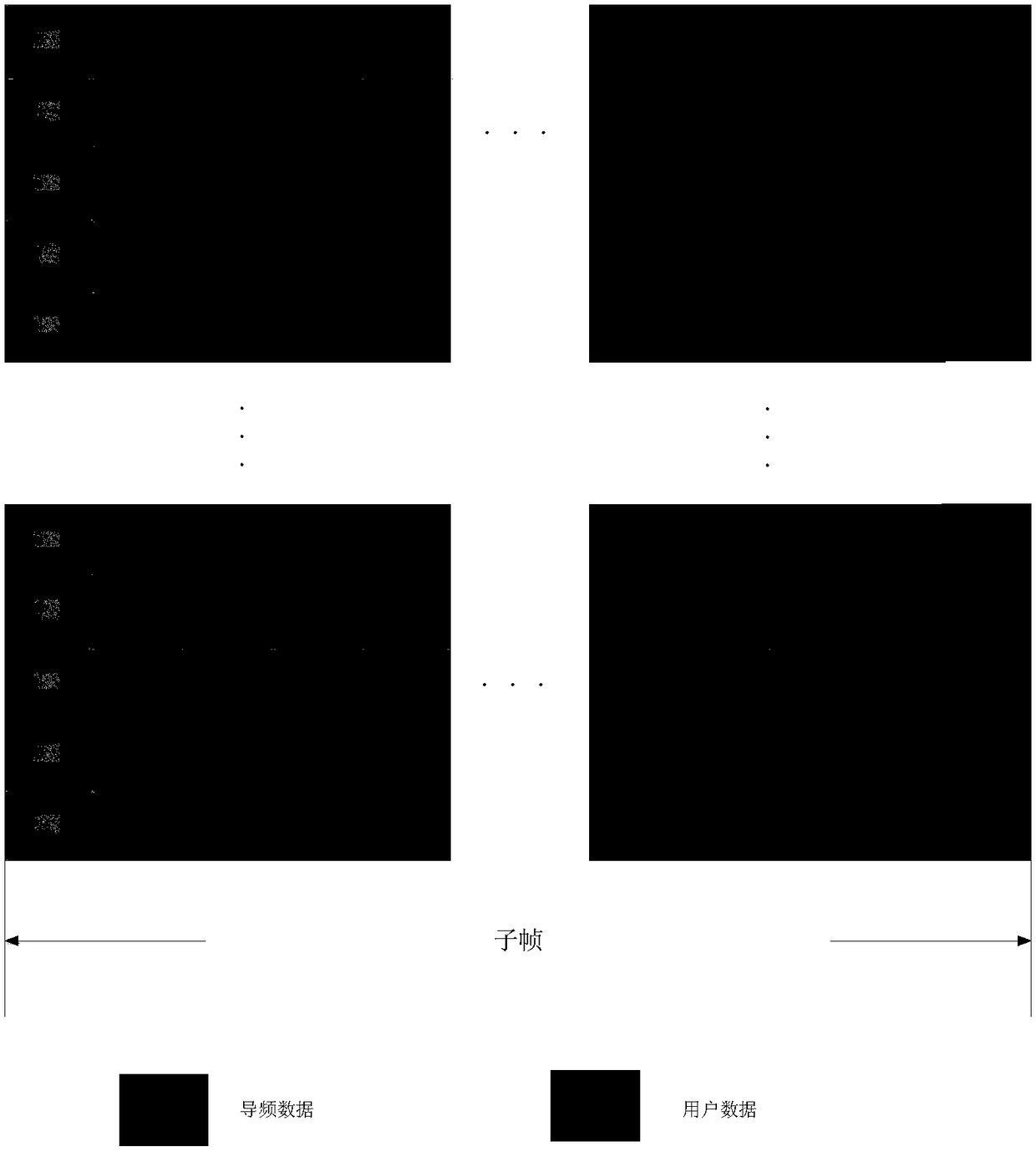
[0092] Statically configure the preamble at the time of cell establishment, such as image 3 shown;

[0093] In subframe n, the base station schedules terminal 1, allocates downlink time-frequency resources for terminal 1, and configures dynamic pilots according to the channel conditions and service types of terminal 1. The pilot pattern is as follows Figure 7 As shown, the relevant information of the dynamic pilot (including indication information such as pilot position and pilot sequence) is delivered to the terminal side through downlink control information. In this embodiment, the service that the terminal needs to implement is the eMBB service, and the channel is assumed to be a slow-changing channel. Therefore, a sparse dynamic pilot pattern is used, that is, the density of the dynamic pilot is relatively sparse. After the pre-pilot of a subframe There are only two dynamic pilots, and dynamic pilots are not set for every subframe, and dynamic pilots can be set at inter...

Embodiment 2

[0096] Statically configure the preamble at the time of cell establishment, such as image 3 shown;

[0097] In subframe n, the base station schedules terminal 1, allocates downlink time-frequency resources for terminal 1, and configures dynamic pilots according to the channel conditions and service types of terminal 1, such as Figure 8 As shown, the dynamic pilot information is sent to the terminal side through the downlink control information. In this embodiment, the service that the terminal needs to implement is the URLLC service, which requires high reliability, so dense dynamic pilot patterns are used, such as Figure 8 As shown, there are 4 dynamic pilots after the pre-pilot of a subframe, and there are 4 dynamic pilots in a subframe every two subframes, compared to Figure 7 In the pilot pattern shown, the density of dynamic pilots is higher, so the terminal can obtain more pilots, realize more accurate channel estimation, and have higher reliability.

[0098] Afte...


PUM


Abstract

The application discloses pilot frequency transmission and receiving methods and devices, and aims to reduce the time delay in reception of a pilot frequency at a terminal in order to improve the channel estimation efficiency based on the pilot frequency. The pilot frequency transmission method comprises the following steps: determining a pilot frequency pattern configured for user equipment, wherein the pilot frequency pattern includes time frequency position information of the pilot frequency, and the time frequency position information of the pilot frequency includes position information ofthe pilot frequency at an initial moment of a subframe; and transmitting the pilot frequency to the user equipment according to the pilot frequency pattern.

Description

technical field [0001] The present application relates to the technical field of communications, and in particular to a pilot sending and receiving method and device. Background technique [0002] With the large-scale commercialization of the fourth-generation mobile communication technology and the continuous growth of mobile services, research on the fifth-generation communication technology (5G) has begun worldwide. 5G is a multi-technology fusion communication that meets the needs of a wide range of data and connection services through technological change and innovation. In the RAN71 meeting, 3GPP established a research project (Study Item, SI) on the standardization of 5G new air interface. According to 5G's division of vertical scenarios, 3GPP mainly conducts research on new air interfaces from three aspects: enhanced mobile broadband (eMBB), ultra-reliable low-latency communications (URLLC) and large-scale Machine Communications (massiveMachine Type Communications,...

Claims


Application Information

Patent Timeline
IPC IPC(8): H04L5/00
CPCH04L5/0048H04L5/0094H04L5/005H04L5/0092H04L5/0007H04L5/0005H04L25/0226H04W72/0446H04B3/10H04W28/0908H04L41/0896
Inventor 王东昊苏进喜
Owner DATANG MOBILE COMM EQUIP CO LTD
Why Eureka
Try Eureka