A thermal desorption device and method for soil remediation

A soil remediation and thermal desorption technology, applied in the restoration of polluted soil and other directions, can solve problems such as secondary pollution, achieve stable and uniform heating, reduce dioxin generation, and increase the intensity of combustion.

Active Publication Date: 2021-07-09
广东禹航环境科技有限公司
View PDF0 Cites 0 Cited by
  • Summary
  • Abstract
  • Description
  • Claims
  • Application Information

AI Technical Summary

Problems solved by technology

[0002] Existing soil thermal desorption often directly uses flames to heat the soil source in the soil thermal desorption chamber at a high temperature, which is likely to cause additional oxidation and decomposition in the soil source due to excessive temperature. and other chemical reactions, causing secondary pollution

Method used


Image

  • A thermal desorption device and method for soil remediation
  • A thermal desorption device and method for soil remediation
  • A thermal desorption device and method for soil remediation

Examples


Embodiment Construction

[0044] The present invention will be further described below in conjunction with the accompanying drawings.

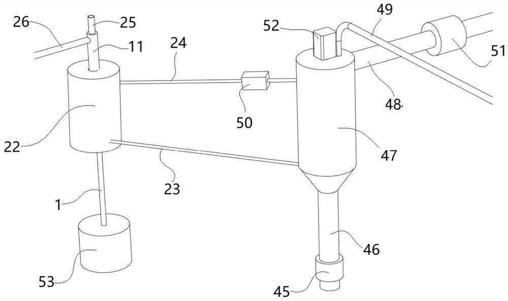
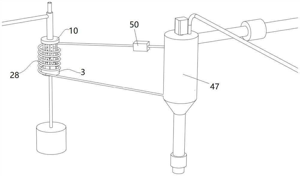
[0045] as attached Figures 1 to 11 Shown is a thermal desorption device for soil remediation, including a thermal oil heating furnace unit 22 and a thermal desorption unit 47;

[0046] The heat-absorbing spiral tube 28 is arranged inside the thermal oil heating furnace unit 22; the heat-releasing spiral tube 62 is arranged inside the heat desorption unit 47; the hot oil outlet end of the heat-absorbing spiral tube 28 passes through the The oil pipe 23 is in communication with the hot oil inlet end of the heat releasing spiral tube 62; Communication connection; the second oil guide pipe 24 is provided with a circulation pump 50 .

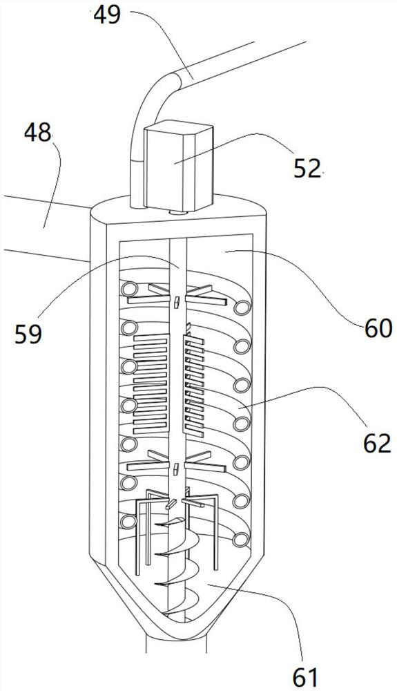
[0047] The thermal desorption unit 47 has a cylindrical airtight container structure, the inner cavity of the thermal desorption unit 47 is a soil thermal desorption cavity 60, and the lower end of the soil thermal desorption cavity 60 is ...


PUM


Abstract

The invention discloses a thermal desorption device for soil restoration, which comprises a thermal oil heating furnace unit and a thermal desorption unit; a heat-absorbing spiral tube is arranged inside the thermal oil heating furnace unit; A heat releasing spiral tube is provided; the hot oil outlet end of the heat absorbing spiral tube communicates with the hot oil inlet end of the heat releasing spiral tube through the first oil guide tube; the cold oil outlet of the heat releasing spiral tube The oil end is communicated with the oil inlet end of the heat-absorbing spiral tube through the second oil guide pipe; the second oil guide pipe is provided with a circulation pump; the structure of the present invention is simple, the combustion in the furnace cavity is uniform, and the heat release is adopted at the same time. The spiral tube heats the soil source stably and evenly, and the temperature control is convenient, avoiding the strong high-temperature heating of the soil source in the soil thermal desorption chamber directly by means of flame.

Description

technical field [0001] The invention belongs to the field of soil purification, in particular to a thermal desorption device and method for soil restoration. Background technique [0002] Existing soil thermal desorption often directly uses flames to heat the soil source in the soil thermal desorption chamber at a high temperature, which is likely to cause additional oxidation and decomposition in the soil source due to excessive temperature. And other chemical reactions, causing secondary pollution. Contents of the invention [0003] Purpose of the invention: In order to overcome the deficiencies in the prior art, the present invention provides a thermal desorption device for soil remediation and a method thereof that heats uniformly and does not cause secondary pollution. [0004] Technical solution: In order to achieve the above purpose, a thermal desorption device for soil remediation of the present invention includes a thermal oil heating furnace unit and a thermal d...

Claims


Application Information

Patent Timeline
Patent Type & Authority Patents(China)
IPC IPC(8): B09C1/06
CPCB09C1/06
Inventor 张兰英
Owner 广东禹航环境科技有限公司
Why Eureka
Try Eureka