Clamp facilitating slope machining of mold

A technology of inclined planes and fixtures, applied in metal processing equipment, metal processing machinery parts, clamping, etc., can solve the problems of inconvenient work, troublesome adjustment of overload, inconvenient adjustment of the demoulding slope, etc., and achieve the effect of increasing the demoulding slope

Inactive Publication Date: 2018-11-06
柳州通亿汽车配件制造有限公司
View PDF7 Cites 17 Cited by
  • Summary
  • Abstract
  • Description
  • Claims
  • Application Information

AI Technical Summary

Problems solved by technology

[0002] Fixture is a device used to fix the processing object in the process of mechanical manufacturing so that it can occupy the correct position to accept construction or testing. In a broad sense, any process in the process is used to install the workpiece quickly, conveniently and safely. The device can be called a fixture. In the production process, in order to facilitate the demoulding of the injection mold during the production process, in terms of design of the existing mold, the index plate and the electromagnetic adsorption plate are fixed on the loading plate, and the load The object plate has a certain inclination angle, that is, the demoulding slope, so that the mold can be ejected smoothly after injection molding, and it is convenient to work, but the existing demoulding slope is not easy to adjust according to the actual production needs, and it is troublesome to adjust the overload, and The positions of the indexing plate and the electromagnetic adsorption plate on the loading plate cannot be adjusted by sliding, which brings inconvenience to the work and affects the work efficiency. Therefore, the present invention proposes a solution to the above problems

Method used


Image

  • Clamp facilitating slope machining of mold
  • Clamp facilitating slope machining of mold
  • Clamp facilitating slope machining of mold

Examples


Embodiment

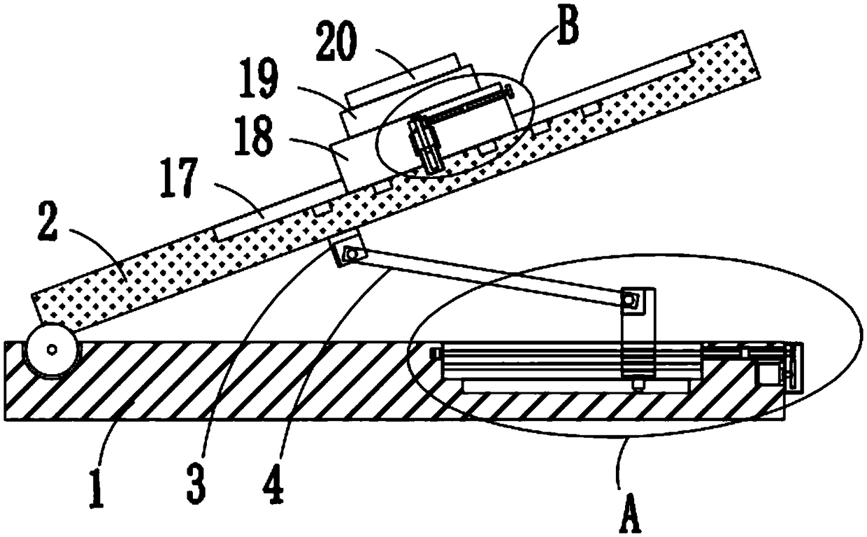
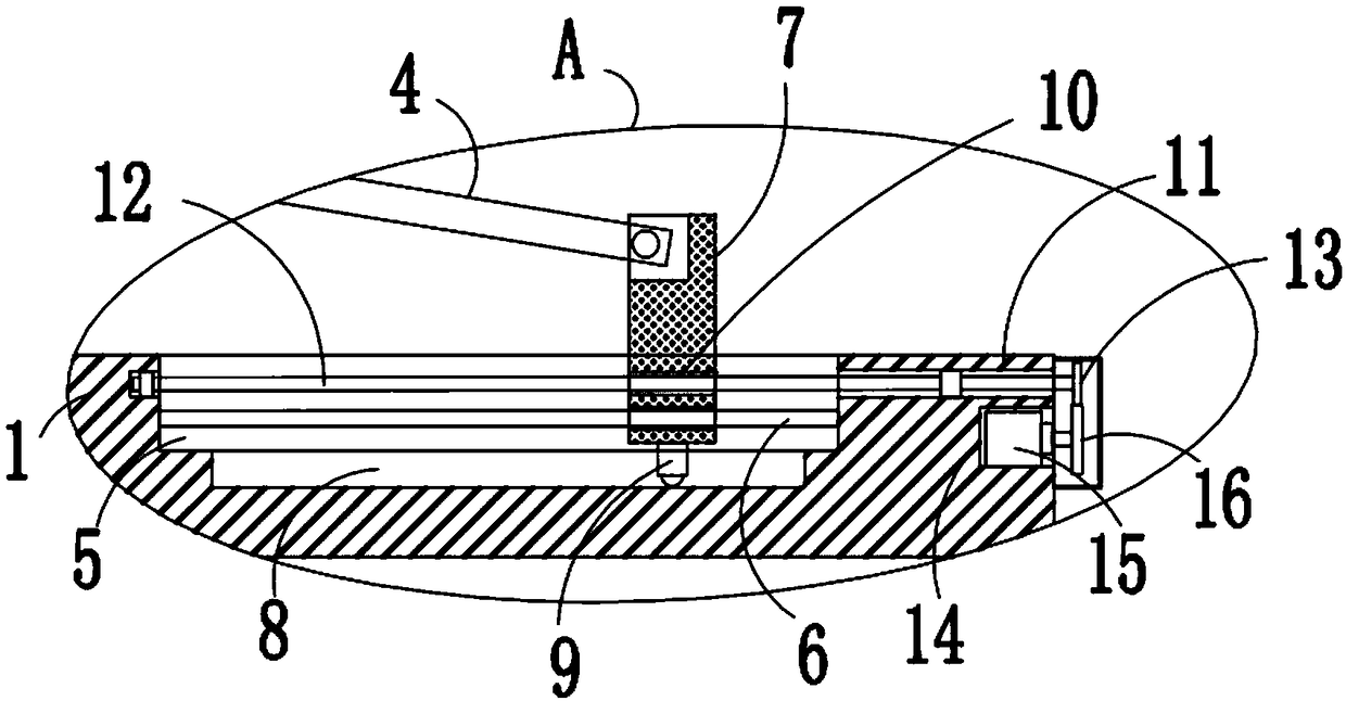
[0024] refer to Figure 1-5In this embodiment, a fixture is proposed to facilitate mold slope processing, including a base 1, the top of the base 1 is hinged with a stage 2, and the stage 2 is inclined, and the bottom of the stage 2 is welded with a connecting seat 3. The connecting rod 4 is installed on the bottom of the connecting seat 3. The connecting rod 4 is inclined. The top of the base 1 is provided with a first chute 5, and the inner wall of the first chute 5 is welded with a first sliding rod 6. A slide slot 5 is slidably installed with a slide seat 7 that is slidably sleeved on the first slide bar 6. The top of the slide seat 7 extends to the outside of the first slide slot 5, and the end of the connecting rod 4 away from the connection seat 3 is rotatably mounted on the On the top of the sliding seat 7, the bottom inner wall of the first chute 5 is provided with a first limiting groove 8, and the bottom of the sliding seat 7 is welded with a first limiting block 9,...


PUM


Abstract

The invention discloses a clamp facilitating slope machining of a mold. The clamp comprises a base, wherein a carrying table is hinged to the top of the base, and the carrying table is obliquely arranged; a connecting base is welded to the bottom of the carrying table, a connecting rod is rotationally arranged at the bottom of the connecting base, and the connecting rod is obliquely arranged; a first sliding groove is formed in the top of the base, a first sliding rod is welded on the inner wall of the first sliding groove, a sliding seat which sleeves the first sliding rod in a sliding mode is arranged in the first sliding groove in a sliding mode, and the top of the sliding seat extends to the outside of the first sliding groove; and the end, far away from the connecting base, of the connecting rod is rotationally arranged at the top of the sliding seat, and a first limiting groove is formed in the inner wall of the bottom of the first sliding groove. According to the clamp, the structure is simple, the operation is simple and convenient, the inclination angle of the carrying table, namely the draft angle can be adjusted conveniently, the position of an indexing plate and the position of an electromagnetic adsorption disc can be adjusted in a sliding mode according to requirements after the draft angle is adjusted, and the draft angle can be fixed so that the work is facilitated.

Description

technical field [0001] The invention relates to the technical field of fixtures, in particular to a fixture that facilitates the processing of inclined planes of molds. Background technique [0002] Fixture is a device used to fix the processing object in the process of mechanical manufacturing so that it can occupy the correct position to accept construction or testing. In a broad sense, any process in the process is used to install the workpiece quickly, conveniently and safely. The device can be called a fixture. In the production process, in order to facilitate the demoulding of the injection mold during the production process, in terms of design of the existing mold, the index plate and the electromagnetic adsorption plate are fixed on the loading plate, and the load The object plate has a certain inclination angle, that is, the demoulding slope, so that the mold can be ejected smoothly after injection molding, and it is convenient to work, but the existing demoulding s...

Claims


Application Information

Patent Timeline
Patent Type & Authority Applications(China)
IPC IPC(8): B23Q3/04B23Q3/154
CPCB23Q3/04B23Q3/1543
Inventor 黄海光罗丙球
Owner 柳州通亿汽车配件制造有限公司
Why Eureka
Try Eureka