
Vibrating motor upper housing automatic alignment machine

A vibrating motor and aligner technology, which is applied to the field of automatic aligning machines on vibration motors, can solve the problems of slow speed, damage, and low efficiency, and achieve the effects of accurate positioning, easy operation and product quality assurance.

Pending Publication Date: 2018-11-06
阜南县特立电子有限公司
View PDF7 Cites 0 Cited by
  • Summary
  • Abstract
  • Description
  • Claims
  • Application Information

AI Technical Summary

Problems solved by technology

[0004] In order to solve the above technical problems, the present invention provides an automatic alignment machine for the upper casing of the vibrating motor to solve the problem of slow speed, low efficiency and damage due to the single injection molding operation mode of the existing motor.

Method used


Image

  • Vibrating motor upper housing automatic alignment machine
  • Vibrating motor upper housing automatic alignment machine
  • Vibrating motor upper housing automatic alignment machine

Examples


Embodiment

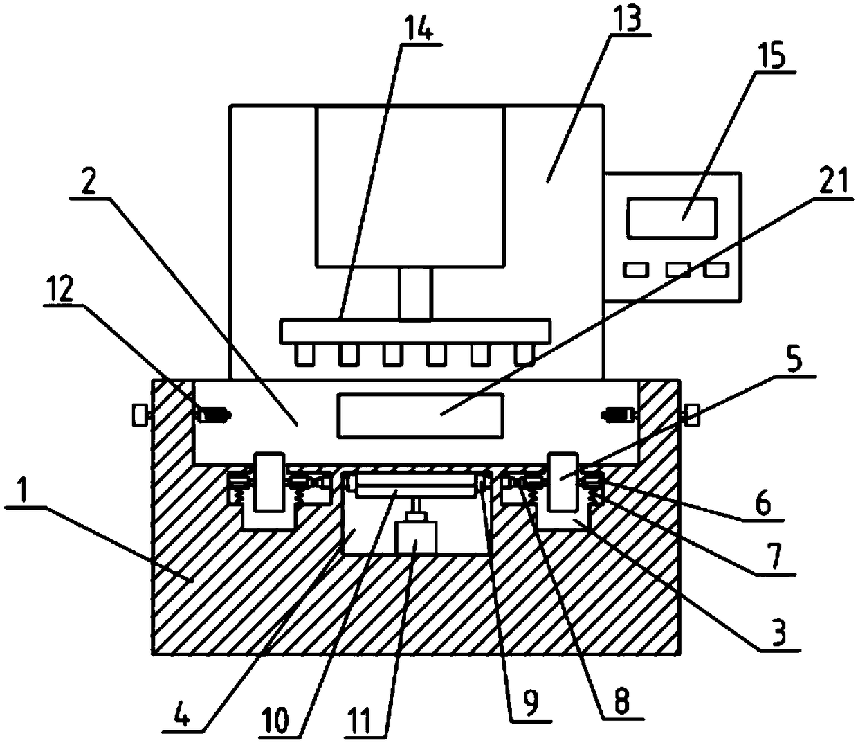
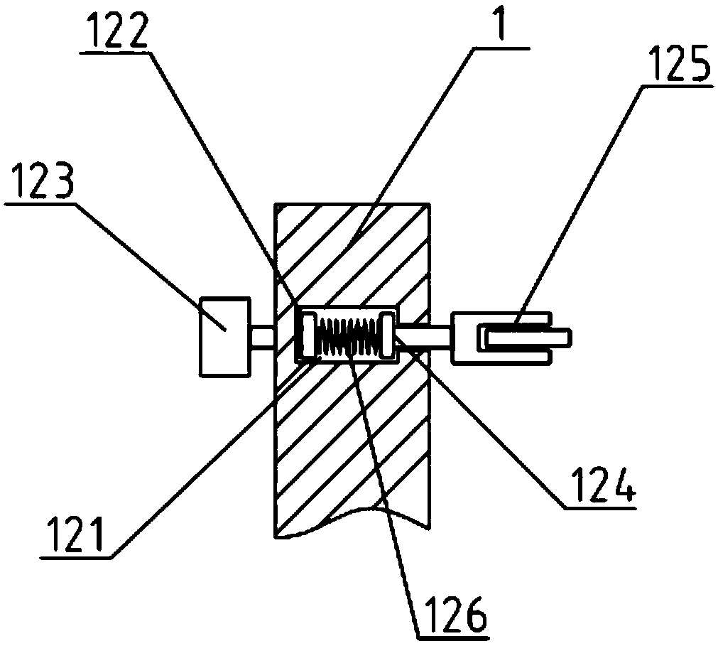
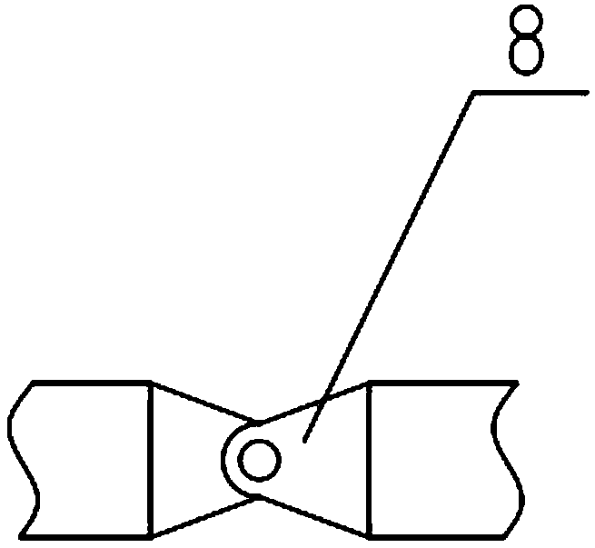
[0019] as attached figure 1 to attach image 3 shown

[0020] The present invention provides an automatic alignment machine for the upper casing of a vibrating motor, which includes a base 1, a positioning groove 2, a dial groove 3, a motor groove 4, a dial 5, a sliding sleeve 6, an elastic member 7, a rotating pair 8, and a gear 9. Gear 2 10, drive motor 11, positioning fixture 12, pneumatic punch 13, punch fixture 14 and control module 15, the upper part of the base 1 is provided with a positioning groove 2 for placing product fixtures, and the lower part of the base 1 is sequentially There are a dial groove 3 and a motor groove 4, wherein the dial groove 3 is located on both sides of the base 1, and the motor groove 4 is located in the middle of the base 1; the dial 5 is located in the dial groove 3, and the rotating shafts on both sides pass through the sliding The sleeve 6 is rotatably connected, and the bottom of the sliding sleeve 6 is supported and connected with an ...


PUM


Abstract

The invention provides a vibrating motor upper housing automatic alignment machine which includes a base, a positioning groove, poke wheel grooves, a motor groove, poke wheels, sliding sleeves, firstelastic parts, revolute pairs, first gears, a second gear, a driving motor, positioning fixtures, a pneumatic punching machine, a punching machine fixture and a control module set. The positioning groove for placing a product fixture is formed in the upper portion of the base, the poke wheel grooves and the motor groove are formed in the lower portion of the base in sequence, wherein the poke wheel grooves are located on the two sides of the base, the motor groove is located in the middle of the base. The poke wheels are located in the poke wheel grooves, and two sides of rotary shafts are connected in a rotating mode through the sliding sleeves. The poke wheels are provided with power through the driving motor, the poke wheels are driven to rotate through the transmission of power from the first gears and the second gear, and the bottom of the product fixture is poked towards the back side until the product fixture reaches a positioning baffle to ensure that the product fixture movesin place, and thus the positioning is more accurate and the product quality is ensured.

Description

technical field [0001] The invention belongs to the technical field of advanced injection molding equipment for motors, and in particular relates to an automatic alignment machine for upper casings of vibrating motors. Background technique [0002] Single motor injection molding operation mode. After the motor is injected, it needs to be separated manually. After separation, it is placed in the turnover box and rubbed against each other, which may cause gaps and poor burrs. The subsequent motor installation needs to be manually installed individually. There are many poor installations, slow speed and low efficiency, and the single injection molding operation of the motor cannot be automated or semi-automated. [0003] Therefore, it is very necessary to invent a kind of vibrating motor upper casing automatic alignment machine. Contents of the invention [0004] In order to solve the above-mentioned technical problems, the present invention provides an automatic alignment m...

Claims


Application Information

Patent Timeline
Patent Type & Authority Applications(China)
IPC IPC(8): B29C45/17
CPCB29C45/1769
Inventor 李伟德管宏伟王丹刘崇根王和平
Owner 阜南县特立电子有限公司
Learn More