A steel pipe end sealing ring and sealing device
A technology of end sealing and sealing ring, which is applied in the direction of engine sealing, engine components, mechanical equipment, etc., can solve the problems of difficult sealing methods and increase in the size of test pressure head, so as to save costs, improve efficiency, and increase usage range effect
- Summary
- Abstract
- Description
- Claims
- Application Information
AI Technical Summary
Problems solved by technology
Method used
Image
Examples
Embodiment 1
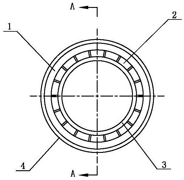
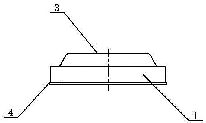
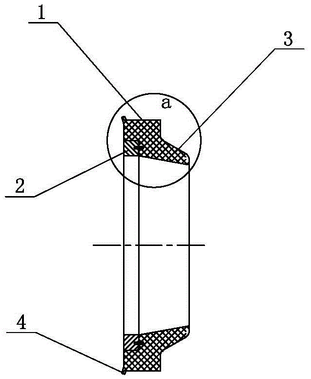
[0042] like figure 1 , 2 , 3, 3a, a steel pipe end sealing ring, including a sealing ring body 1, a support block 2, the support block 2 is a fan ring, the junction of an end face of the sealing ring body 1 and its inner circumferential surface, an annular groove is arranged The support block 2 is evenly distributed in the annular groove, the support block 2 body is provided with a pin, the pin connects the support block 2 and the sealing ring body 1 together, and the end face of the sealing ring body 1 without the support block 2 is provided with a distance The end face and the steel pipe sealing skirt 3 extending obliquely to the steel pipe sealing surface, the sealing ring body 1 is provided with the junction of the end face of the support block 2 and its outer circumferential surface, and an end face sealing skirt 4 extending obliquely away from the end face is provided;
[0043] The angle formed between the edge of the steel pipe sealing skirt 3 against the surface of th...
Embodiment 2
[0045] like Figure 4 , 4a , 4b, set the pressure-bearing steel pipe (ie pressure test pipe 9) to be inserted from left to right. The sealing device using the steel pipe end sealing ring of the first embodiment includes a steel pipe end sealing ring, a sealing head 5, and a positioning sleeve 6, and the positioning sleeve 6 is matched with the sealing head 5; the inner cavity of the sealing head 5 is provided with a groove 51. The sealing ring at the end of the steel pipe is placed in the left part of the groove 51 (the pressure test tube is inserted from left to right), and the end face of the supporting block 2 on the sealing ring at the end of the steel pipe is closely fitted with the inner surface of the left end of the groove 51; the end face is sealed The outer edge of the skirt 4 is in close contact with the inner surface of the peripheral wall of the groove 51;
[0046] The left part of the positioning sleeve 6 is provided with a limit ring 61; the right part of the ...
Embodiment 3
[0049] like Figure 5 , 6 , 7, a steel pipe end sealing ring, including a sealing ring body 1, a support block 2, the support block 2 is a fan ring, the junction of an end face of the sealing ring body 1 and its inner circumferential surface is provided with an annular groove, The support blocks 2 are evenly distributed in the annular groove, and the body of the support block 2 is provided with pins, which connect the support blocks 2 and the sealing ring body 1 together. The steel pipe sealing skirt 3 extending obliquely to the sealing surface of the steel pipe, the sealing ring body 1 is provided with the junction of the end face of the support block 2 and the outer circumferential surface, and the end face sealing skirt 4 extending obliquely away from the end face is provided;
[0050] On the end face of the sealing ring body 1 where the steel pipe sealing skirt 3 is provided, a ring of supporting grooves 8 is arranged, and the bottom of the supporting groove 8 is in the s...
PUM
 Abstract
Description
Claims
Application Information
 - R&D
- Intellectual Property
- Life Sciences
- Materials
- Tech Scout
- Unparalleled Data Quality
- Higher Quality Content
- 60% Fewer Hallucinations
Browse by: Latest US Patents, China's latest patents, Technical Efficacy Thesaurus, Application Domain, Technology Topic, Popular Technical Reports.
© 2025 PatSnap. All rights reserved.Legal|Privacy policy|Modern Slavery Act Transparency Statement|Sitemap|About US| Contact US: help@patsnap.com


