Camera assembly, vehicle comprising the camera assembly and adjusting method of the camera assembly

A camera component and camera technology, applied in electrical components, image communication, vehicle parts, etc., can solve the problem of inconvenient adjustment of the camera

Active Publication Date: 2018-11-06
HUAQIN TECH CO LTD
View PDF5 Cites 4 Cited by
  • Summary
  • Abstract
  • Description
  • Claims
  • Application Information

AI Technical Summary

Problems solved by technology

[0005] The technical problem to be solved by the present invention is to provide an adjustment method for a camera assembly, a car containing it, and a camera assembly in order to overcome the disadvantage that the camera in the prior art is inconvenient to adjust.

Method used


Image

  • Camera assembly, vehicle comprising the camera assembly and adjusting method of the camera assembly
  • Camera assembly, vehicle comprising the camera assembly and adjusting method of the camera assembly
  • Camera assembly, vehicle comprising the camera assembly and adjusting method of the camera assembly

Examples


Embodiment 1

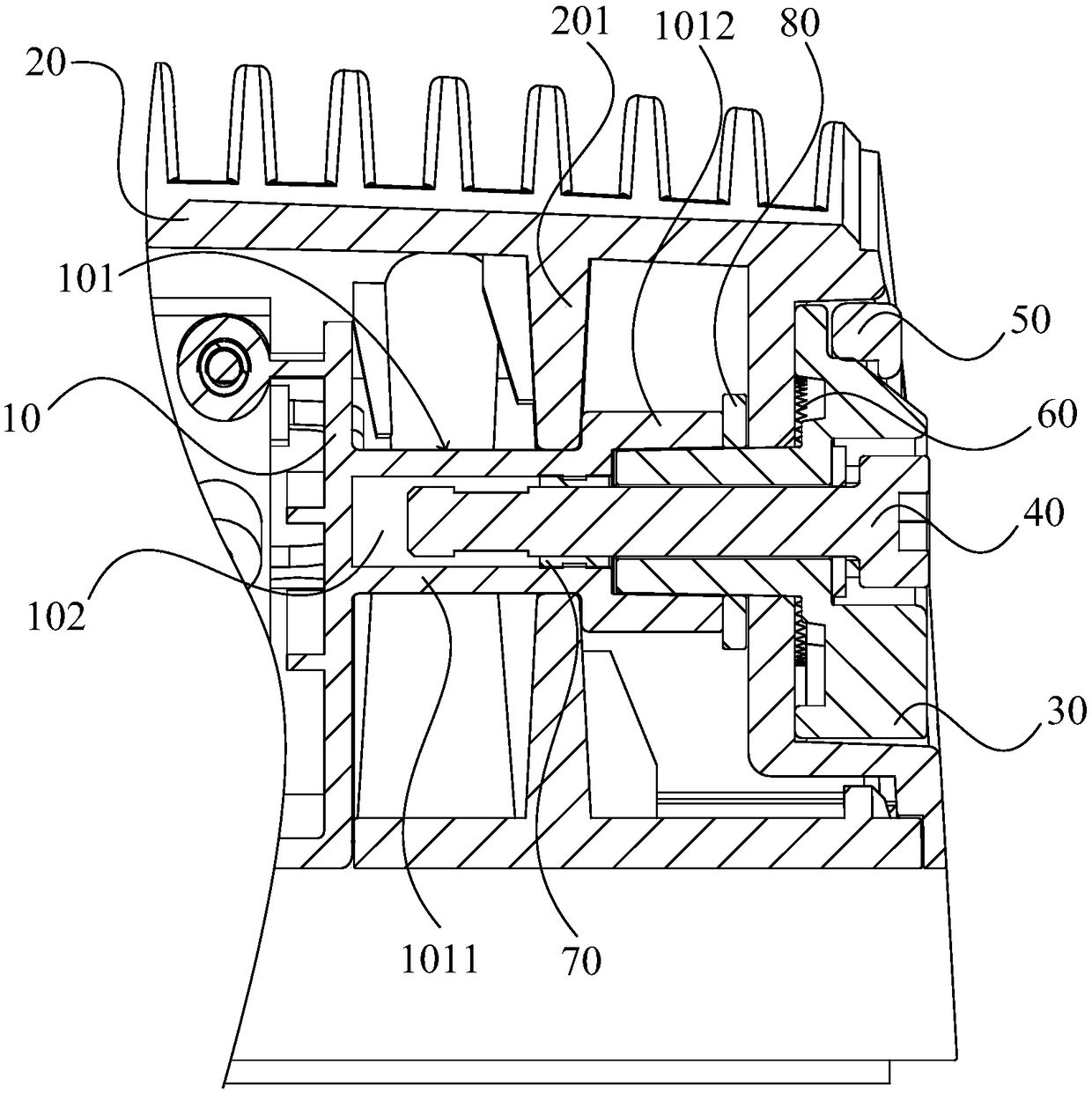
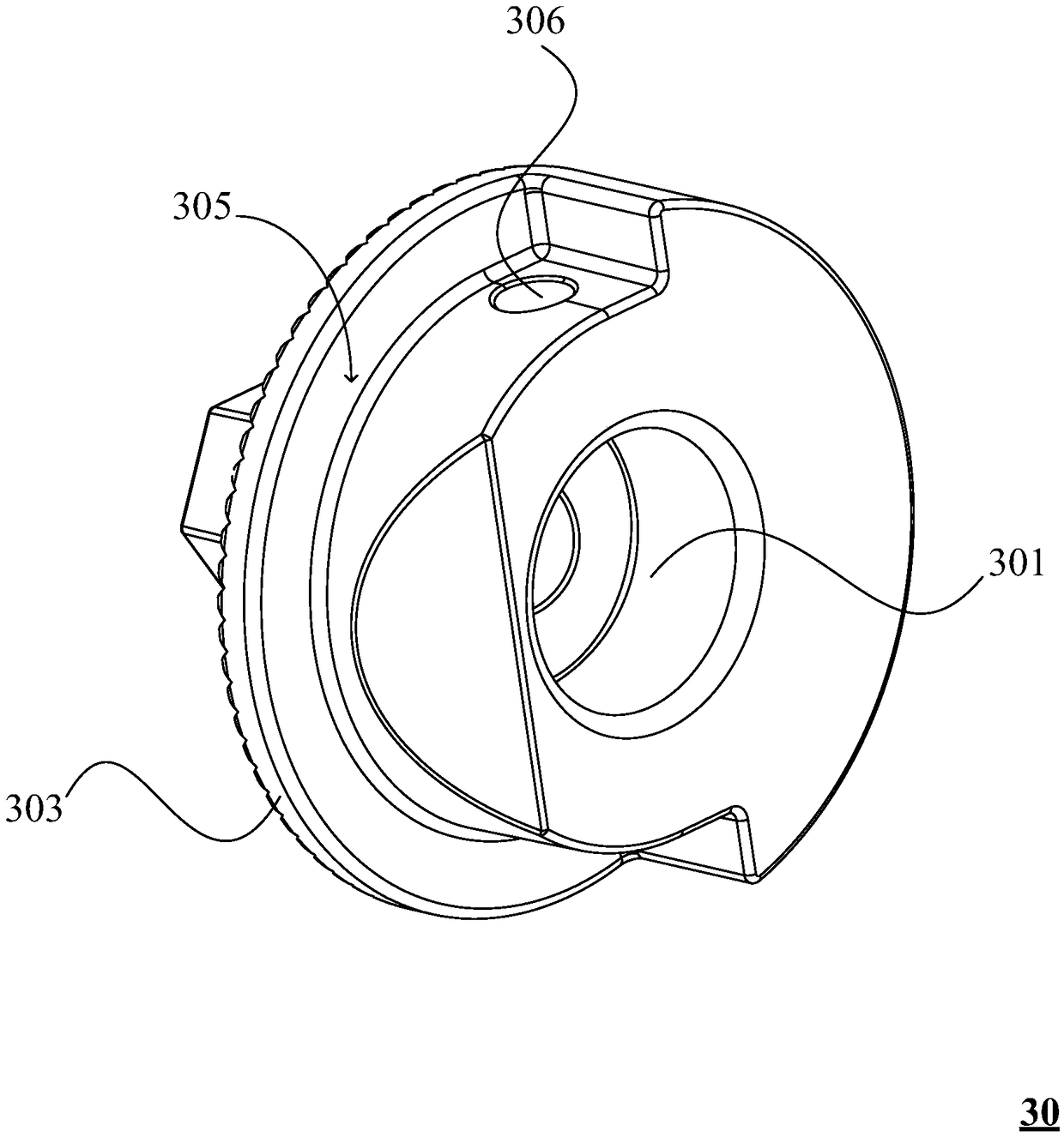
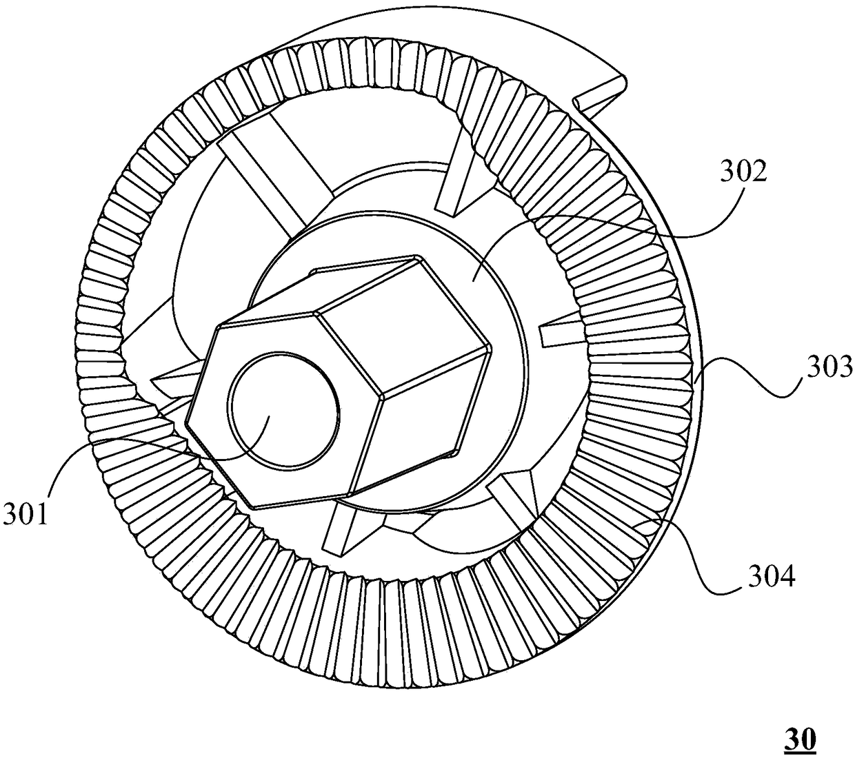
[0069] The present embodiment provides a camera assembly, which can be understood with reference to 1-5. The camera assembly includes a camera mount 10, a camera (not shown in the figure), a housing 20, an adjustment seat 30 and a fastener 40, and the camera mount One end of 10 is clamped on the housing 20, and the other end extends to the outside of the housing 20. The camera is located at the other end of the camera mount 10, and one of the side walls of the camera mount 10 is provided with a wall extending toward the side wall of the housing 20. The extension portion 101 has an accommodating hole 102 along the extension direction, and the extension portion 101 is located inside the housing 20 . The adjustment seat 30 has a head end and a tail end along the extension direction, the head end of the adjustment seat 30 is passed through the housing hole 102 through the side wall of the housing 20, and the tail end of the adjustment seat 30 is attached to the side wall of the hou...

Embodiment 2

[0084] This embodiment discloses a method for adjusting a camera assembly, the camera assembly is the camera assembly in Embodiment 1, refer to Image 6 It should be understood that the adjustment method includes the following steps:

[0085] Step 100, unscrew the fastener;

[0086] Step 200, apply an external force to the force application part along the force application direction, so as to make the adjustment seat and the extension part rotate relative to the casing.

[0087] In this embodiment, when the fastener is unscrewed, the casing, the camera mounting seat and the adjusting seat are still connected together. When an external force is applied to the force application part, the adjusting seat and the extension part rotate relative to the casing. By rotating the adjusting seat The position of the camera mount can be adjusted more conveniently, so that the position of the camera can be adjusted more conveniently.


PUM


Abstract

The invention discloses a camera assembly, a vehicle comprising the camera assembly and an adjusting method of the camera assembly. The camera assembly comprises a camera installation seat, a camera and a housing. An extending part is equipped with an accommodating hole along an extending direction. The extending part is positioned in the interior of the housing. The camera assembly also comprisesan adjusting seat and a fastening part. The head end of an adjusting seat is arranged in the accommodating hole in a penetrating manner through the side wall of the housing. The tail end of the adjusting seat is attached onto the side wall of the housing and equipped with a first connecting hole which penetrates through the adjusting seat along the extending direction. The tail end of the adjusting seat is also equipped with a force-applying part. The fastening part penetrates through the first connecting hole and the accommodating hole and is in threaded connection with the extending part and can switch bewteen the fastening state and the rotatably-loosening state. In the rotatably-loosening state, the tail end of the fastening part and the head end of the adjusting seat are both in theextending part. When the force-applying part applies external force, the adjusting seat and the extending part rotate relative to the housing. The position of the camera in the camera assembly is convenient to adjust.

Description

technical field [0001] The invention relates to the field of automobiles, in particular to a camera assembly, an automobile containing the same, and a method for adjusting the camera assembly. Background technique [0002] There is usually a camera assembly on the front windshield of the car to observe the driving conditions on the road. Wherein, the camera assembly includes a camera, an inner shell and an outer shell. Wherein, the camera is installed on the inner shell through the camera mounting seat, and the outer shell is provided with a shell, which has heat dissipation and protection functions, and the camera faces outside. [0003] In order to adapt to the windshield angle of different cars and ensure that the camera observes the ground at a reasonable angle, it is usually necessary to adjust the camera. However, in the prior art, when adjusting the camera, the housing needs to be removed first, and then the camera can be adjusted, which is inconvenient to operate. ...

Claims


Application Information

Patent Timeline
Patent Type & Authority Applications(China)
IPC IPC(8): B60R11/04H04N5/225
CPCB60R11/04B60R2011/008B60R2011/0001H04N23/51H04N23/50H04N23/57
Inventor 李思敏
Owner HUAQIN TECH CO LTD
Why Eureka
Try Eureka