Oil tank for dry type lubricating system

A technology of lubricating system and lubricating oil tank, which is applied to lubricating parts, pressure lubricants, engine lubrication, etc., can solve the problems of inconvenient maintenance and complex structure, and achieve the effect of convenient follow-up maintenance.

Pending Publication Date: 2018-11-06
芜湖钻石航空发动机有限公司
View PDF7 Cites 2 Cited by
  • Summary
  • Abstract
  • Description
  • Claims
  • Application Information

AI Technical Summary

Problems solved by technology

[0003] The lubricating oil tank used for the dry lubrication system of the existing avia

Method used


Image

  • Oil tank for dry type lubricating system
  • Oil tank for dry type lubricating system

Examples


Embodiment Construction

[0020] The specific embodiment of the present invention will be described in further detail by describing the embodiments below with reference to the accompanying drawings, the purpose is to help those skilled in the art to have a more complete, accurate and in-depth understanding of the concept and technical solutions of the present invention, and contribute to its implementation.

[0021] It should be noted that in the following embodiments, the "first" and "second" do not represent an absolute distinction in structure and / or function, nor do they represent a sequence of execution, but are only for Easy to describe.

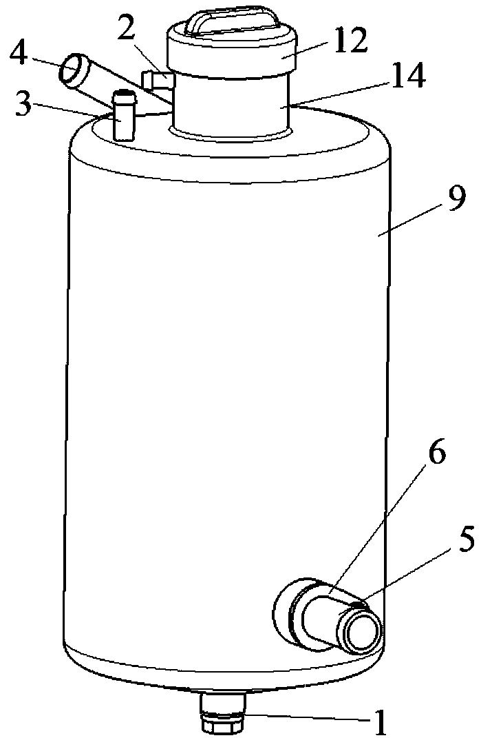
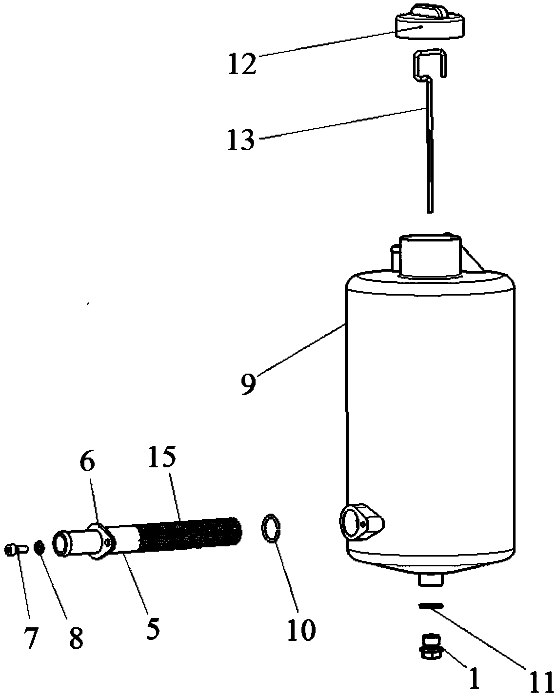
[0022] Such as Figure 1 to Figure 2 As shown, the present invention provides a lubricating oil tank for a dry lubrication system, which includes a lubricating oil tank body 9 and an oil outlet pipe joint. The oil outlet pipe joint is detachably connected to the lubricating oil tank body 9. Filter screen 15 for filtering oil.

[0023] Specifically, as figur...


PUM


Abstract

The invention discloses an oil tank for a dry type lubricating system. The oil tank comprises an oil tank body and an oil outlet pipe joint; the oil outlet pipe joint is detachably connected with theoil tank body, and a filter net for filtering oil is arranged on the oil outlet pipe joint. According to the oil tank for the dry type lubricating system, the detachable oil outlet pie joint integrated with the filter net is adopted, and the subsequent maintaining is facilitated.

Description

technical field [0001] The invention belongs to the technical field of aircraft, in particular, the invention relates to a lubricating oil tank for a dry lubricating system. Background technique [0002] At present, most piston engines use a wet oil pan lubrication system, and the oil pan is used as an oil storage device. Engines using this lubrication system are mainly used in automobiles, agricultural vehicles and other industries. The engine layout space is relatively large, which not only increases the engine capacity The weight and size increase the position of the center of gravity of the engine, and at the same time, phenomena such as "oil churning" will occur, which will affect the working performance of the engine. The dry oil sump lubrication system uses an external lubricating oil tank as an oil storage device, which can not only lower the center of gravity of the engine, but also make the structure of the engine flatter. Compared with the traditional automobile ...

Claims


Application Information

Patent Timeline
IPC IPC(8): F01M11/00F01M11/03
CPCF01M11/0004F01M11/03F01M2011/0083F01M2011/031F01M2011/0029
Inventor 熊骏华郑君刘刚胡崇波卢东亮卞少春周佳
Owner 芜湖钻石航空发动机有限公司
Why Eureka
Try Eureka