Carrying module for overflow valve assembly line

An assembly line and overflow valve technology, which is applied in the directions of transportation and packaging, conveyor objects, conveyors, etc., can solve the problems of easy clamping and falling off, and achieve the effect of not easy to fall off, low production cost, and convenient follow-up maintenance.

Pending Publication Date: 2022-05-10
济南隆利液压装置有限责任公司
View PDF0 Cites 0 Cited by
  • Summary
  • Abstract
  • Description
  • Claims
  • Application Information

AI Technical Summary

Problems solved by technology

[0004] The purpose of the present invention is to solve the problem that the clamping is easy to fall off in the prior art, and propose a handling module for the overflow valve assembly line

Method used


Image

  • Carrying module for overflow valve assembly line
  • Carrying module for overflow valve assembly line
  • Carrying module for overflow valve assembly line

Examples


Embodiment

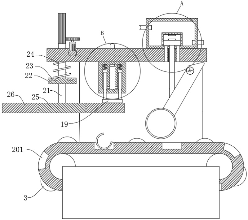
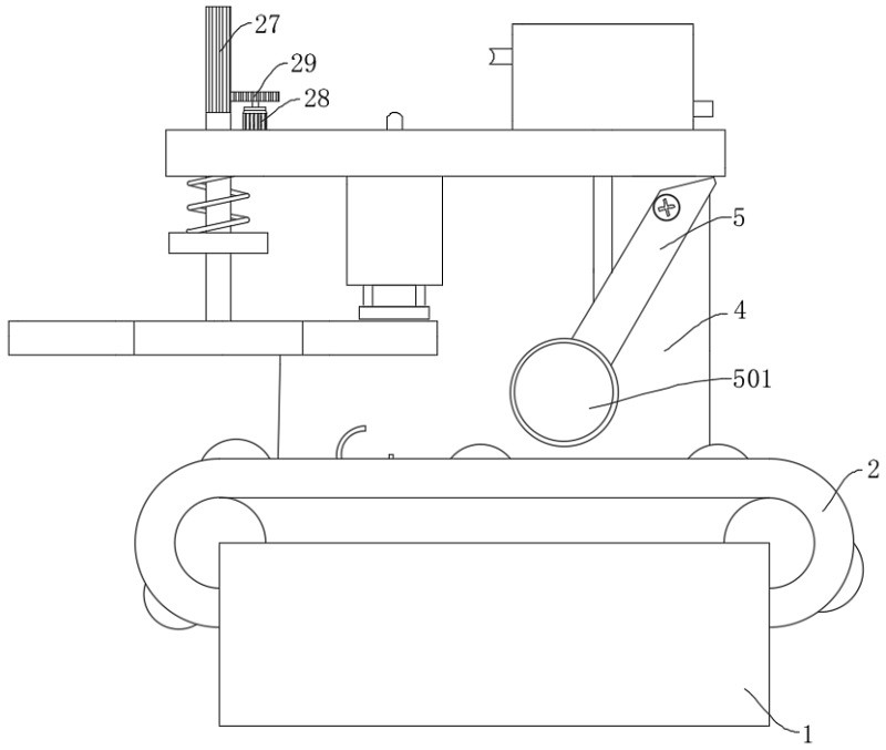
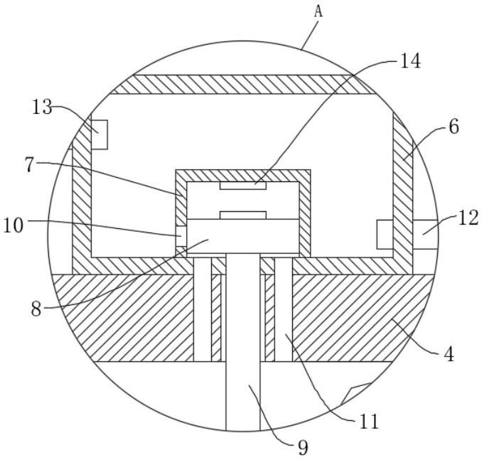
[0028] refer to Figure 1-4 , used for the handling module on the overflow valve assembly line, including a conveyor 1 and a conveyor belt 2 arranged on the conveyor 1. The top surface of the conveyor 1 is fixedly installed with a support frame 4, and one side of the support frame 4 is provided with Trigger assembly, and the top of the support frame 4 is fixedly installed with a closed box 6, the bottom surface of the inner wall of the closed box 6 is fixedly installed with a sealing cover 7, the interior of the sealing cover 7 is slidably connected with a piston plate 8, and the surface of the support frame 4 is slidably connected with a movable Rod 9, the top of the movable rod 9 is fixedly connected with the bottom surface of the piston plate 8, and the movable rod 9 is vertically slidably connected to the inside of the support frame 4 to ensure that the movable rod 9 can reciprocate in the linear direction, and the bottom of the movable rod 9 The end is in contact with the...


PUM


Abstract

The invention discloses a carrying module for an overflow valve assembly line, and belongs to the field of carrying modules. The carrying module for the overflow valve assembly line comprises a conveyor and a conveying belt arranged on the conveyor, a supporting frame is fixedly installed on the top face of the conveyor, a trigger assembly is arranged on one side of the supporting frame, and a closed box is fixedly installed at the top of the supporting frame; by arranging the closed box, the sealing cover and the piston plate, the position of the spring is positioned and detected, the spring can be conveniently clamped subsequently, and compared with infrared laser positioning in the prior art, the device is simple in structure, low in manufacturing cost and convenient to maintain subsequently; and through cooperation with mechanism assemblies such as protruding blocks, rolling wheels, a closed box and an air cylinder, the device can carry a single spring at a fixed point, adsorption is stable, and the spring is not prone to falling off.

Description

technical field [0001] The present invention relates to the technical field of handling modules, in particular to a handling module used on an assembly line of an overflow valve. Background technique [0002] The relief valve is a hydraulic pressure control valve, which mainly plays the role of constant pressure relief in hydraulic equipment, and has the functions of voltage stabilization and safety protection of system unloading. The relief valve is a wiring used in many equipment. , Therefore, the market has a large demand for it, and the production capacity is also high. The relief valve generally includes: main valve core, return spring, valve seat and other components. When assembling the relief valve, a manipulator is required to adjust the relief valve Each part is assigned to a storage box, and then installed by workers. [0003] However, the handling of the existing manipulator has certain defects, because the existing manipulator handles the accessories by clampin...

Claims


Application Information

Patent Timeline
Patent Type & Authority Applications(China)
IPC IPC(8): B65G47/92
CPCB65G47/92B65G2201/0214
Inventor 郭凯王亮
Owner 济南隆利液压装置有限责任公司
Why Eureka
Try Eureka