
An Optical Modeling Method for Condenser Lens Construction in Concentrating and Heat Collecting System

A technology of concentrating heat and modeling methods, applied in the direction of concentrating mirrors, optics, optical components, etc., can solve problems such as large errors and difficulty in achieving theoretical concentrating effects, achieve high interception efficiency, realize structural optimization and efficiency improvement Effect

Inactive Publication Date: 2020-11-10
LANZHOU JIAOTONG UNIV
View PDF4 Cites 0 Cited by
  • Summary
  • Abstract
  • Description
  • Claims
  • Application Information

AI Technical Summary

Problems solved by technology

The traditional process of making the primary reflector into a micro-arc has a large error, and in addition to various error items when the project is formed, it is difficult to achieve the theoretical light-gathering effect

Method used


Image

  • An Optical Modeling Method for Condenser Lens Construction in Concentrating and Heat Collecting System
  • An Optical Modeling Method for Condenser Lens Construction in Concentrating and Heat Collecting System
  • An Optical Modeling Method for Condenser Lens Construction in Concentrating and Heat Collecting System

Examples


Embodiment

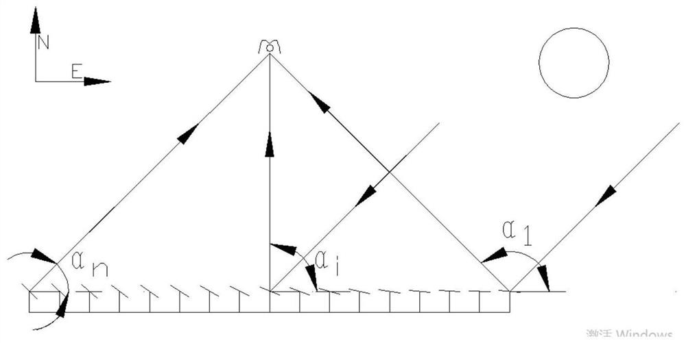
[0069] Taking the linear Fresnel concentrating system as an example, except for the secondary reflector, the other installation parameters of the system are shown in Table 1: take the east-west direction of the axis plane of the primary reflector as the x-axis, and take the line segment between the center points of the mirrors on the east and west edges The vertical line is the y-axis. (unit: mm)

[0070] Table 1

[0071]

[0072] All primary mirror elements take the centerline of the opening plane of the secondary reflector as the aiming line.

[0073] The modeling of a secondary reflector consists of the following steps

[0074] Table 2

[0075]

[0076]

[0077] Calculating the Opening Size of the Secondary Mirror

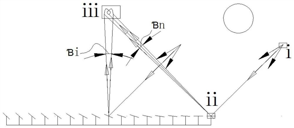
[0078] Such as figure 1 As shown, use σ sun is the root mean square of the solar aperture angle, σ specularity is the root mean square error of the mirror surface shape, σ slope is the root mean square of the specular reflection error, σ trac...

Embodiment 2

[0108] The traditional secondary reflector adopts the CPC structure of involute + parabola. The specific modeling method is as follows:

[0109] Involute part:

[0110] Taking the outer diameter of the metal inner tube of the vacuum heat collecting tube as the base circle and its center as the origin to establish a rectangular coordinate system, the parametric coordinate equation of the involute in the left half of the CPC can be obtained:

[0111] x=-R(sin t-tcost)

[0112] y=-R(cost+tsin t)

[0113] In the formula, R is the radius of the metal inner tube of the vacuum heat collector, and t is the parameter of the involute equation. Rotate the involute by α around the center of the circle so that the point t=t0 on the involute is on the CPC central axis, and t0 and α respectively satisfy the following

[0114] equation:

[0115]

[0116] x=-R(sin t 0 -t 0 cost 0 )

[0117] y=R(cost 0 +t 0 sin t 0 )

[0118] -(xcosα-ysinα)=0

[0119] In the formula, L is the su...


PUM


Abstract

The invention relates to an optical modeling method for a collecting lens structure in a light and heat collecting system. The method is suitable for modeling a secondary mirror in a linear Fresnel isosteric focusing heat collecting system, and especially suitable for a slot or dish-type light collecting system. The secondary mirror no longer depends on a reflecting surface in a special shape, andcan be quickly modeled according to actual conditions, such as primary mirror parameters, a heat collecting tube specification, an installation process and the like, has high intercepting efficiency,and achieves structural optimization and efficiency improvement.

Description

technical field [0001] The invention relates to an optical modeling method for the structure of a concentrating mirror in a concentrating and heat-collecting system, which is suitable for the modeling of a secondary reflector in a heat-collecting system of linear Fresnel type equilinear focusing. Especially suitable for trough or dish concentrating systems. Background technique [0002] As a component of the linear Fresnel concentrating heat collection system, the secondary reflector has an important influence on the concentrating efficiency. The traditional secondary reflector basically adopts the CPC structure of involute + parabola. The special line shape limits the flexibility of the design of the secondary reflector. Once the size of the heat collecting tube and the gap between it and the CPC are determined, the opening of the CPC is also determined. size. Although CPC has a high convergence rate in theory, it is often based on the existing small aperture The CPC ca...

Claims


Application Information

Patent Timeline
Patent Type & Authority Patents(China)
IPC IPC(8): G02B27/00G02B19/00G06F30/20
CPCG02B19/0019G02B19/0038G02B27/0012G06F30/20
Inventor 王成龙梁飞巩景虎马军
Owner LANZHOU JIAOTONG UNIV
Learn More