Camera module, assembly method and electronic device

A technology of camera module and assembly method, which is applied in the direction of TV, electrical components, image communication, etc., can solve problems such as weak rigidity, achieve the effects of reducing accumulation, reducing assembly tolerance, and ensuring assembly accuracy

Pending Publication Date: 2018-11-06
NINGBO SUNNY OPOTECH CO LTD
View PDF5 Cites 6 Cited by
  • Summary
  • Abstract
  • Description
  • Claims
  • Application Information

AI Technical Summary

Problems solved by technology

Since the flexible board is a flexible material with low rigidity, this patent application introduces a reinforcing steel plate to increase the rigidity of the camera module, and from the attached figure 1 It can be seen that the connecting post on the installation base passes through the soft board and is fixed in the reinforcement steel plate, and the reinforcement steel plate only serves as a fixed support for the soft board and the installation base

Method used


Image

  • Camera module, assembly method and electronic device
  • Camera module, assembly method and electronic device
  • Camera module, assembly method and electronic device

Examples


Embodiment 1

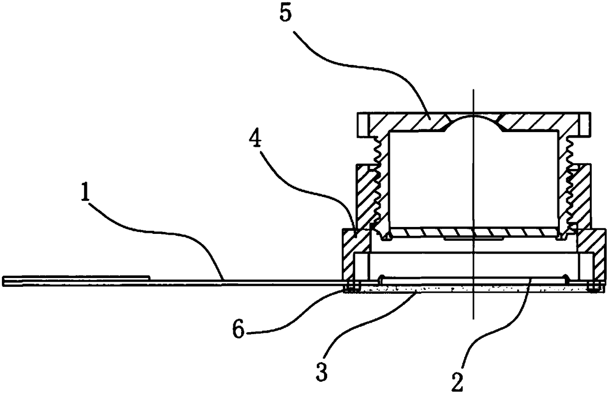
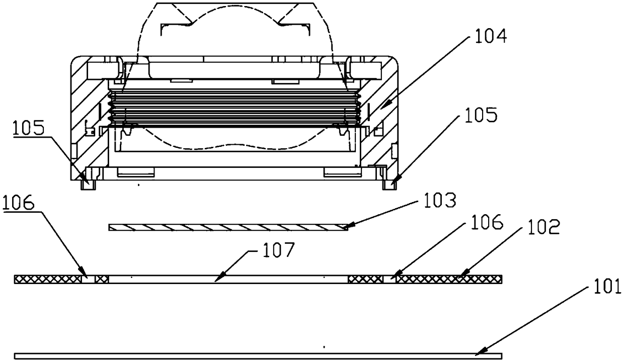
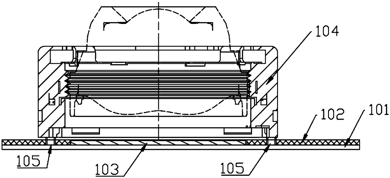
[0032] like figure 2 and image 3 As shown, the camera module provided in this embodiment includes: a reinforcing plate 101 , a circuit board 102 , a photosensitive chip 103 and a lens assembly 104 .

[0033] Wherein, the reinforcing plate 101 may be a metal material, for example, but not limited to, it is implemented as a metal product such as a steel sheet obtained by a process such as stamping. The reinforcing plate 101 has a very high flatness. In addition to supporting and fixing the camera module, it can also provide a very flat reference surface for the photosensitive chip 103 and the lens assembly 104. The photosensitive chip 103 and the lens assembly 104 Mounting based on this reference plane can greatly reduce assembly tolerances.

[0034] The number of circuit boards 102 is not limited. The camera module provided in this embodiment includes one circuit board 102, which is provided with at least one hollow area 107 and at least one positioning hole 106, and is att...

Embodiment 2

[0045] On the basis of Embodiment 1, this embodiment provides a camera module, the camera module includes a reinforcing plate, a circuit board, a photosensitive chip, and a lens assembly, wherein the reinforcing plate, the circuit board, and the photosensitive chip are the same as those in Embodiment 1. are the same, and will not be repeated here.

[0046] The camera module provided in this embodiment is an autofocus module, wherein the lens assembly includes:

[0047] a drive assembly, the drive assembly includes a base, a lens carrier, and a drive member for driving the lens to move, and a surface of the base is provided with at least one positioning post extending outward;

[0048] a lens, the lens is mounted on the lens carrier of the drive assembly;

[0049] a filter element, mounted on the base of the drive assembly;

[0050] The lens and the filter element are sequentially located on the photosensitive path of the photosensitive chip.

[0051] It is worth mentioning ...

Embodiment 3

[0061] On the basis of Embodiment 1, this embodiment provides a camera module, the camera module includes a reinforcing plate, a circuit board, a photosensitive chip, and a lens assembly, wherein the reinforcing plate, the circuit board, and the photosensitive chip are the same as those in Embodiment 1. are the same, and will not be repeated here.

[0062] The camera module provided in this embodiment is a fixed-focus module, wherein the lens assembly includes:

[0063] a base, a surface of the base is provided with at least one positioning post extending outward;

[0064] a filter element, the filter element is arranged on the other end face of the base opposite to the positioning column;

[0065] a lens, the lens is arranged on the base;

[0066] The lens and the filter element are sequentially located on the photosensitive path of the photosensitive chip.

[0067] Specifically, the filter element is a filter, and the lens and the filter element are sequentially located o...


PUM


Abstract

The invention discloses a camera module, comprising: a reinforcing plate; at least one circuit board, wherein the circuit board is provided with at least one hollow area and at least one positioning hole attached to the surface of the reinforcing plate; at least one photosensitive chip, wherein the photosensitive chip is attached to the surface of the reinforcing plate through the hollow area on the circuit board; and at least one lens component, wherein the lens component comprises at least one positioning column corresponding to the positioning hole, and the positioning column penetrates through the positioning hole on the circuit board to be attached to the surface of the reinforcing plate so as to assemble the lens component. The invention further discloses an assembly method of the camera module. By adoption of the camera module and the assembly method, the assembly tolerance of the camera module can be reduced to improve the optical performance of the camera module.

Description

technical field [0001] The invention relates to the field of optical imaging, in particular to a camera module, an assembling method of the camera module and an electronic device based on the camera module. Background technique [0002] Optical performance is an important performance of the camera module. The optical performance of the camera module is not only affected by the performance of the lens, photosensitive chip and other components, but the assembly accuracy also affects the optical performance of the camera module, that is, the reduction of the assembly accuracy will directly lead to The optical performance of the camera module is reduced. [0003] The existing module assembly process is as follows: a photosensitive chip is attached to a circuit board, and after it is connected to the circuit board, a base is set on the circuit board, and a filter element and a filter element are installed on the base. driver. In the entire assembly process, there are many assem...

Claims


Application Information

Patent Timeline
Patent Type & Authority Applications(China)
IPC IPC(8): H04N5/225
CPCH04N23/50H04N23/55
Inventor 高春娇方银丽张王振
Owner NINGBO SUNNY OPOTECH CO LTD
Why Eureka
Try Eureka