Tail pressing looper

A looper and tail-type technology, applied to bending workpieces, metal processing equipment, metal rolling, etc., can solve problems such as easy whipping and splitting

Pending Publication Date: 2018-11-09
XINJIANG BAYI IRON & STEEL
View PDF7 Cites 0 Cited by
  • Summary
  • Abstract
  • Description
  • Claims
  • Application Information

AI Technical Summary

Problems solved by technology

[0002] The upper part of the looper used in the prior art has a developed structure, and the problems of whipping and splitting are easy to occur when the tail of the rolled piece passes through the looper, resulting in the cracked tail of the rolled piece being easily left in the guide and causing Steel Rolling Accident

Method used


Image

  • Tail pressing looper
  • Tail pressing looper

Examples


Embodiment Construction

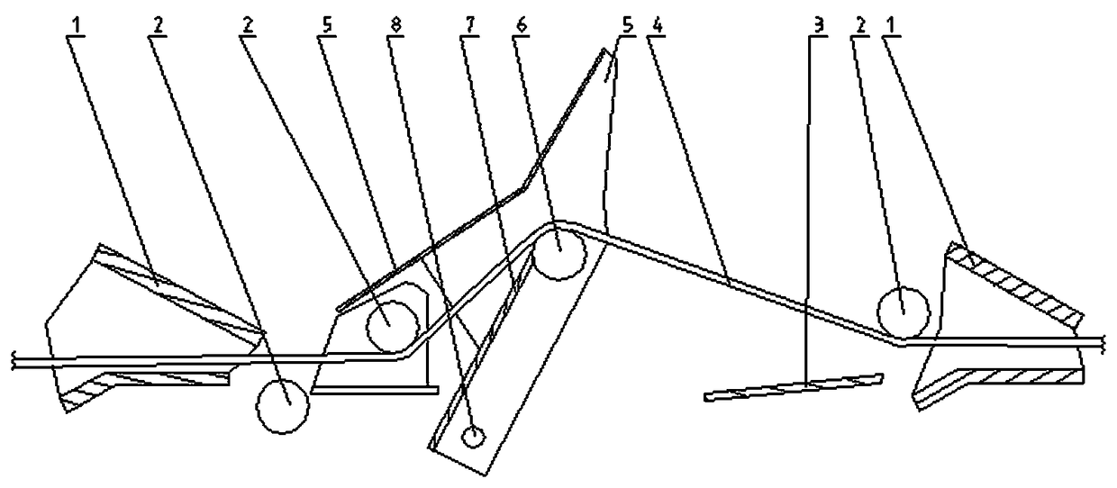
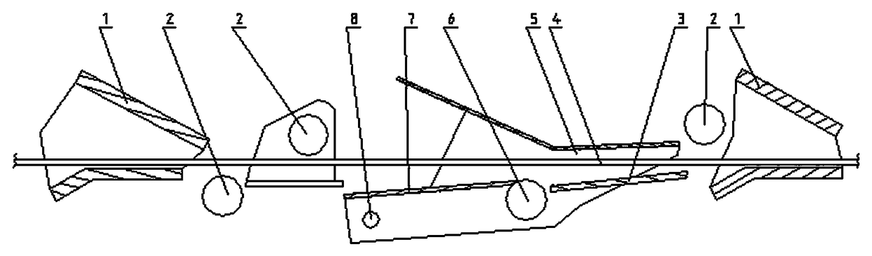
[0009] like figure 1 , figure 2 As shown, the tail-pressing type looper of the present invention mainly includes a looper roller 6, a movable guide plate 7, a fixed guide roller 2, and a looper shaft 8. The looper guide box 5 that doubles as the looper arm is housed on the looper shaft 8, the looper roller 6, the movable guide plate 7. The looper guide box 5 is a groove structure with a lower opening.

[0010] like figure 1 , figure 2 As shown, in order to enable the looper guide box to better cover the tail of the rolled piece 4, a lower guide plate 3 that can be covered by the head of the looper guide box 5 is also installed on the lower right side of the looper roller 6. .

[0011] like figure 1 , figure 2 As shown, the fixed guide roll 2 assists the looper roll 6 to adjust the stable tension of the rolling piece 4 during the rolling process. At the same time, when the looper roller 6 is at the lowest position, the fixed guide roller 2, the guide box 1, the loope...


PUM


Abstract

The invention discloses a tail pressing looper in the technical field of steel rolling. A looper roll and a looper guide plate are installed on a looper guide box also as a looper arm, fixing guide rollers and guide boxes are installed on the front and rear ends of a looper shaft; the looper guide box whose opening faces downward is in a groove structure, and can rotate up and down with the looperroll; and the looper guide box and the looper roll can descend to the lowest position to cover a rolling tail in the smallest space when the rolling tail passes through the looper. Therefore, steel-heaping accidents caused by whipping and splitting of the rolling tails can be effectively prevented.

Description

technical field [0001] The invention relates to a tail-pressing type looper, which belongs to the technical field of steel rolling. Background technique [0002] The upper part of the looper used in the prior art has a developed structure, and the problems of whipping and splitting are easy to occur when the tail of the rolled piece passes through the looper, resulting in the cracked tail of the rolled piece being easily left in the guide and causing Heap of steel rolling accidents. Contents of the invention [0003] The object of the present invention is to provide a tail-pressing type looper, which can effectively prevent the pile-up accident caused by whipping and splitting at the tail of the rolled piece. [0004] The purpose of the present invention is achieved in this way, a tail-pressing type looper, which mainly includes a looper roller, a movable guide plate, a fixed guide roller, and a looper shaft, and a combination As the looper guide box of the looper arm, t...

Claims


Application Information

Patent Timeline
Patent Type & Authority Applications(China)
IPC IPC(8): B21B41/00
CPCB21B41/00
Inventor 李保国
Owner XINJIANG BAYI IRON & STEEL
Why Eureka
Try Eureka