Refrigerator

A refrigerator and box technology, applied in the field of home appliances, can solve problems such as inability to use, occupy, and large storage space, and achieve the effect of avoiding condensation

Inactive Publication Date: 2018-11-09
HAIER SMART HOME CO LTD +1
6 Cites 2 Cited by

AI-Extracted Technical Summary

Problems solved by technology

That is to say, the space where the beam extends backward to the depth of the storage compartme...

Method used

Further, in the refrigerator 100 of this embodiment, the bottom end of the inner wall of the first door body 21 is provided with a first push-off structure 211, which is configured to: when the second door body 22 is opened, the first push-back structure 211 of the top-to-turn beam 30 One end 31, so that the second end 32 of the rotating beam 30 rotates toward the direction of the second door body 22 centered on the rotating shaft 33; When the first door body 21 is opened, it pushes against the second end 32 of the swivel beam 30 , so that the first end 31 of the swivel beam 30 rotates toward the first door body 21 around the rotating shaft 33 . The lower part of the door seal 60 at the bottom of the inner wall of the first door body 21 is also provided with a first stopper 212, which is configured to reset the turning beam 30 to a vertical state when the first door body 21 is closed; and the inner wall of the second door body 22 The upper part of the top door seal 60 is also provided with a second stopper 222 configured to reset the turning beam 30 to a vertical state when the second door body 22 is closed. The first top-opening structure 211 and the second top-opening structure 221 can automatically drive the turning beam 30 to rotate accordingly according to the open state of the first door body 21 and the second door body 22, effectively ensuring that the first door body 21 and the second door body The body 22 is opened smoothly; while the first block 212 and the second block 222 can automatically reset the turning beam 30 according to the closed state of the first door body 21 and the second door body 22, effectively ensuring that the first door body 21 and the second door body 22 are closed. The airtightness of the second door body 22. The arrangement of the door seal 60 and the turning beam 30 effectively improves the sealing degree of the first door body 21 and the second door body 22 , and reduces the loss of cold energy at the first door body 21 and the second door body 22 .
It should be noted that the swivel beam 30 is a cuboid as a whole, and its long sides are correspondingly set with the width of the first drawer 11 and the second drawer 12, which can ensure that there will be no gap between the swivel beam 30 and the lateral sides of the casing 10. Leakage of cooling. Specifically, the long sides of the turning beam 30 may have arc-shaped transitions. The bottom front end of the first drawer 11 has a first recess 111 for accommodating the swivel beam 30 ; and the top front end of the second drawer 12 has a second recess 121 for accommodating the swivel beam 30 . In this way, only a small portion of space at the bottom front end of the first drawer 11 and the top front end of the second drawer 12 can be occupied, avoiding occupying the overall depth space of the first drawer 11 and the second drawer 12, and effectively increasing the storage volume. Since the top of the second drawer 12 is open, the second recess 121 is actually formed by the abdication of the front ends of the two side walls of the second drawer 12 .
Specifically, the first push-back structure 211 and the second push-back structure 221 all include: a thimble 24 and a spring 23, and one end of the spring 23 of the first push-back structure 211 is fixed to the first door body 21, and the other end It is fixed with the thimble 24 ; one end of the spring 23 of the second push-off stru...

Abstract

The invention provides a refrigerator. The refrigerator includes a box body, a first door body, a second door body, and a rotating beam. The interior of the box body is provided with a first drawer and a second drawer that are vertically adjacent to each other to respectively define a first space and a second space; the first door body and the second door body are respectively disposed on front surfaces of the first drawer and the second drawer to operably open and close the first space and the second space; the rotating beam is used for enclosing a gap between the first door body and the second door body, a first end of the rotating beam closes to the first door body, a second end of the rotating beam closes to the second door body, and both ends of a rotating shaft of the rotating beam is respectively fixed to both sides of the inner wall of the body box; when the first door is opened, the first end of the rotating beam rotates in the direction of the first door body centering on therotating shaft to avoid the bottom of the first drawer; and when the second door body is opened, the second end of the rotating beam rotate in the direction of the second door centering on the rotating shaft to avoid the upper edge of the second drawer. The refrigerator of the invention enables the depth of the first drawer and the second drawer to be increased, thus effectively increasing a storage volume of a storage space.

Application Domain

Lighting and heating apparatusSupport

Technology Topic

Refrigerated temperatureElectrical and Electronics engineering

Image

  • Refrigerator
  • Refrigerator
  • Refrigerator

Examples

  • Experimental program(1)

Example Embodiment

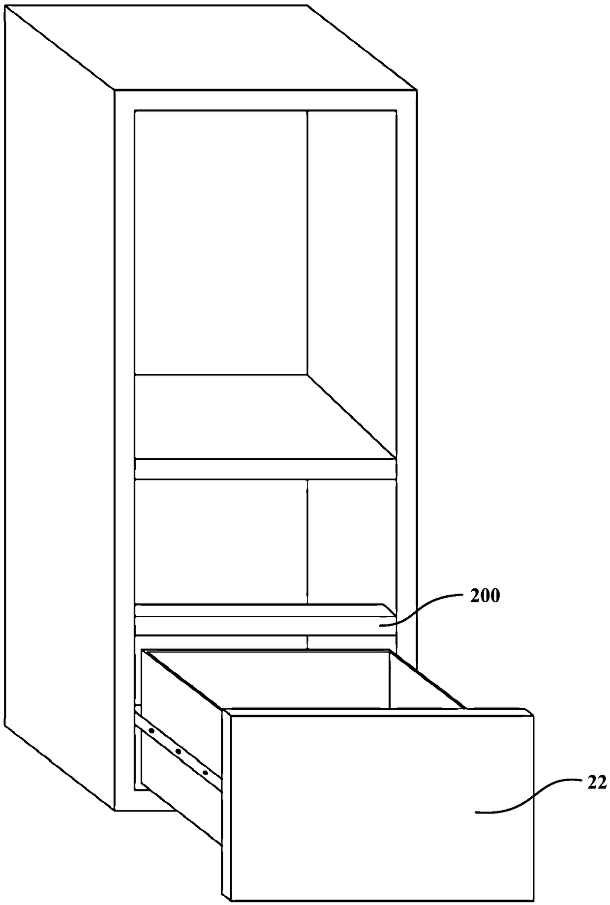
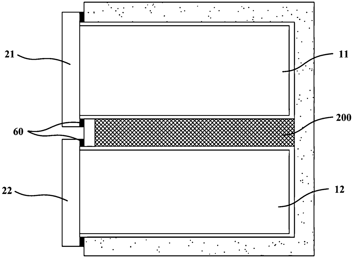
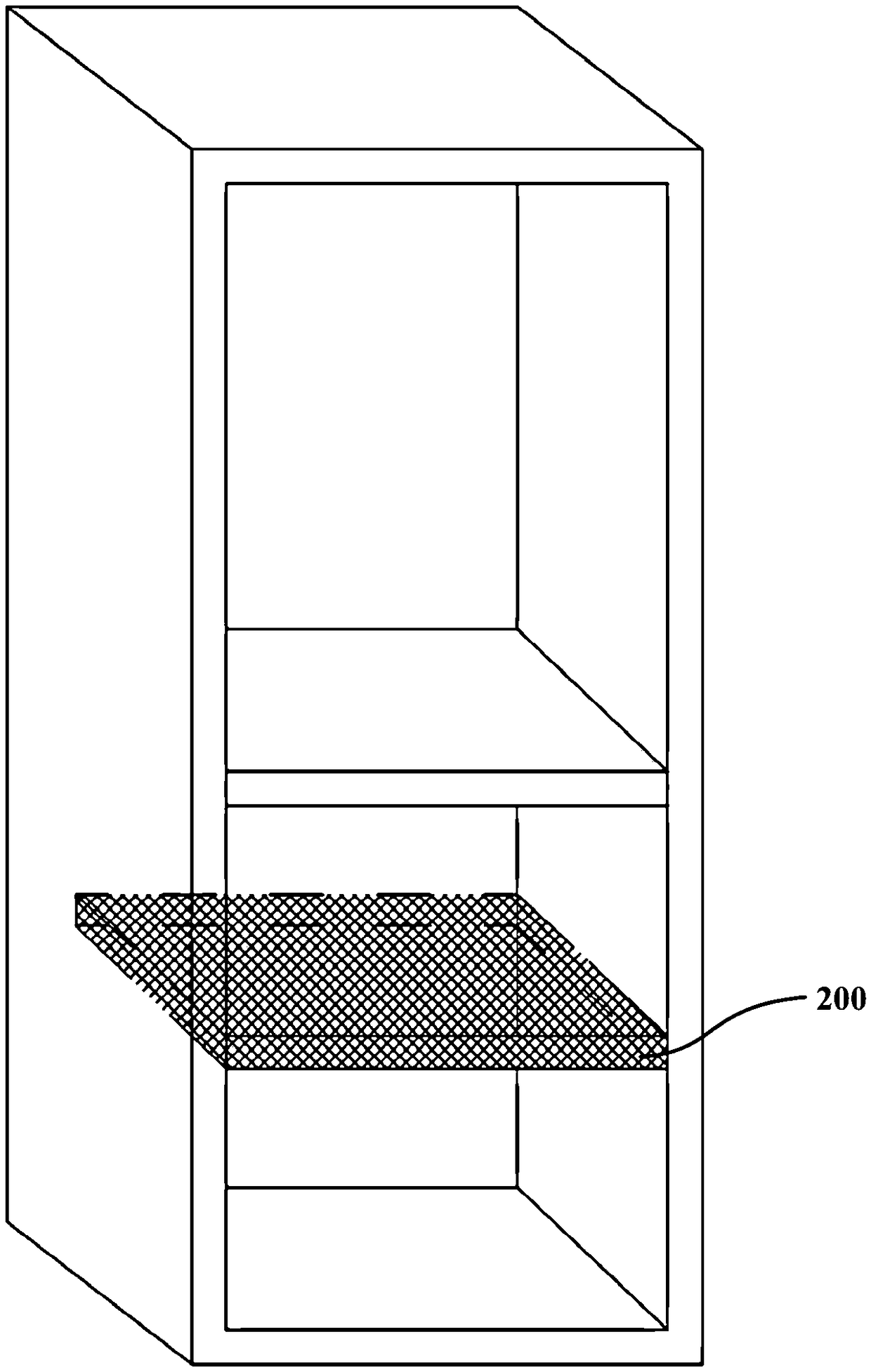
[0031] figure 1 It is a schematic diagram of the airtight drawer door of the refrigerator in the prior art when it is opened, figure 2 It is a schematic diagram of the sealed drawer door of a refrigerator in the prior art when it is closed, image 3 It is a schematic structural diagram of a cross beam 200 of a refrigerator in the prior art. Such as Figure 1 to Figure 3 As shown, when the refrigerator in the prior art is provided with the first drawer 11 and the second drawer 12 adjacent to each other up and down, the first door body 21 of the first drawer 11 and the second door body of the second drawer 12 A fixed cross beam 200 is arranged between 22, so that a part of the door seal 60 on the first drawer 11 and the second drawer 12 can be pressed onto the cross beam 200 here, so as to avoid leakage of cold energy at the door seal 60. In order to ensure the thermal insulation of the door seal 60, the minimum length of the pressed portion between the door seal 60 and the beam 200 is 8 mm. And in order to ensure the opening space of the first drawer 11 and the second drawer 12, especially in order to ensure the opening space of the lower second drawer 12, the concealed handle is arranged at the edge of the upper first drawer 11. At this time, in order to open the lower second drawer 12. It is necessary to have a certain space distance to ensure that the user's hand can reach in. The height of the beam 200 is generally 55mm. But because the beam 200 exists, and considering that the two adjacent first drawers 11 and the second drawer 12 can be pulled out without obstacles, the bottom surface of the upper first drawer 11 is higher than the upper surface of the beam 200, and the lower second drawer 12 The upper edge is lower than the lower surface of the beam 200. That is, the space of the cross beam 200 that extends backward in the depth direction of the storage compartment to the rear wall of the inner liner of the refrigerator is unusable and occupies a relatively large storage space.
[0032] This embodiment provides a refrigerator 100, Figure 4 Is a schematic diagram of the refrigerator 100 when the first door body 21 and the second door body 22 are closed according to an embodiment of the present invention, Figure 5 Is a partial structural diagram of a refrigerator 100 according to an embodiment of the present invention, Image 6 Is a schematic diagram of the opening process of the first door body 21 of the refrigerator 100 according to an embodiment of the present invention, Figure 7 It is a schematic diagram of the opening process of the second door 22 of the refrigerator 100 according to an embodiment of the present invention. Such as Figure 4 to Figure 7 As shown, the refrigerator 100 of this embodiment may generally include: a box body 10, a first door body 21, a second door body 22 and a rotating beam 30.
[0033] Wherein, the box body 10 is provided with a first drawer 11 and a second drawer 12 adjacent to each other up and down to define the first space and the second space, respectively. In addition, such as Figure 5 As shown, other storage spaces may be provided above the first drawer 11 and the second drawer 12 separately. The number and structure of storage spaces defined inside the box 10 can be configured according to requirements. The storage space can be configured as a refrigerated space, a freezer space, a temperature-changing space or a fresh-keeping space according to different uses. Each storage space can be divided into multiple storage areas by dividing plates, and shelves or drawers are used to store items. Specifically, the first space and the second space in the refrigerator 100 of this embodiment may both be set as freezing spaces, and the storage space above the first drawer 11 and the second drawer 12 may be set as refrigerating spaces.
[0034] Such as Figure 4 As shown, the first door body 21 and the second door body 22 may be respectively arranged on the front surfaces of the first drawer 11 and the second drawer 12 to operably open and close the first space and the second space. The rotating beam 30 is configured to close the gap between the first door body 21 and the second door body 22, the first end 31 of the rotating beam 30 is close to the first door body 21, and the second end 32 of the rotating beam 30 is close to the second door The two ends of the rotating shaft 33 of the rotating beam 30 are respectively fixed to both sides of the inner wall of the box body 10. When the first door body 21 is opened, the first end 31 of the rotating beam 30 rotates in the direction of the first door body 21 with the rotating shaft 33 as the center, so as to avoid the bottom of the first drawer 11; when the second door body 22 is opened , The second end 32 of the rotating beam 30 rotates in the direction of the second door 22 with the rotating shaft 33 as the center, so as to avoid the upper edge of the second drawer 12. Such as Figure 4 As shown, in fact, when the rotating beam 30 is in a vertical state, the first end 31 of the rotating beam 30 is close to the first door body 21, and the second end 32 of the rotating beam 30 is close to the second door body 22. In addition, when the rotating beam 30 is in a vertical state, the dimension in the height direction is larger than the dimension in the depth direction. In a specific embodiment, when the first door body 21 or the second door body 22 is opened, the rotation angle range of the rotating beam 30 is 0° to 75°.
[0035] In the refrigerator 100 of this embodiment, by setting the rotating beam 30, there is no need to provide a fixed cross beam 200. When the first door body 21 and the second door body 22 are opened, the rotating beam 30 can be rotated accordingly to ensure that the first door The body 21 and the second door body 22 can be opened undisturbed, which occupies a smaller space than the existing cross beam 200, which can increase the depth of the first drawer 11 and the second drawer 12, and effectively increase the storage space. Volume.
[0036] It should be noted that the rotating beam 30 is a rectangular parallelepiped as a whole, and its long sides are arranged corresponding to the widths of the first drawer 11 and the second drawer 12, which can ensure that there is no leakage of cold energy between the rotating beam 30 and the lateral sides of the box 10 . Specifically, the long side of the rotating beam 30 may have an arc transition. The bottom front end of the first drawer 11 has a first recess 111 for accommodating the rotating beam 30; and the top front end of the second drawer 12 has a second recess 121 for accommodating the rotating beam 30. In this way, only a small part of the space at the bottom front end of the first drawer 11 and the top front end of the second drawer 12 can be occupied, and the overall depth space of the first drawer 11 and the second drawer 12 can be avoided, and the storage volume can be effectively increased. Since the top of the second drawer 12 is open, the second recess 121 is actually formed by the front ends of the two side walls of the second drawer 12 giving way.
[0037] Such as Figure 4 , Image 6 with Figure 7 As shown, the bottom end of the inner wall of the first door body 21 is provided with a first top opening structure 211, which is configured to top the first end 31 of the rotating beam 30 when the second door body 22 is opened, so that the The second end 32 rotates in the direction of the second door 22 with the rotating shaft 33 as the center. A second top opening structure 221 is provided on the top end of the inner wall of the second door 22, which is configured to top the second end 32 of the rotating beam 30 when the first door 21 is opened, so that the first end 31 of the rotating beam 30 It rotates in the direction of the first door body 21 with the rotating shaft 33 as the center.
[0038] Specifically, the first top opening structure 211 and the second top opening structure 221 both include a thimble 24 and a spring 23, and one end of the spring 23 of the first top opening structure 211 is fixed to the first door body 21, and the other end is connected to the thimble 24. Fixed; One end of the spring 23 of the second top opening structure 221 is fixed to the second door 22, and the other end is fixed to the thimble 24. Both the first door body 21 and the second door body 22 include a door seal 60, which is arranged around the inner walls of the first door body 21 and the second door body 22, and the door seal 60 can ensure the first door body 21 and the second door body The airtightness of 22 places avoids cold leakage. In addition, one end of the spring 23 of the first top opening structure 211 is fixed to the door seal 60 at the bottom of the inner wall of the first door body 21; one end of the spring 23 of the second top opening structure 221 is fixed to the door seal on the top of the inner wall of the second door body 22 60.
[0039] Figure 8 Is a schematic diagram of the closing process of the first door 21 of the refrigerator 100 according to an embodiment of the present invention, Picture 9 It is a schematic diagram of the closing process of the second door 22 of the refrigerator 100 according to an embodiment of the present invention. Such as Figure 8 with Picture 9 As shown, the lower part of the door seal 60 at the bottom of the inner wall of the first door body 21 is also provided with a first stopper 212 configured to reset the rotating beam 30 to a vertical state when the first door body 21 is closed. The upper part of the door seal 30 on the top of the inner wall of the second door body 22 is also provided with a second stopper 222 configured to reset the rotating beam 30 to a vertical state when the second door body 22 is closed.
[0040] In a specific embodiment, the outside of the rotating beam 30 is made of polystyrene material, and the inside of the rotating beam 30 is a foamed structure made of heat-insulating material, such as a vacuum insulation board. Preferably, heating wires (not shown in the figure) are arranged inside the rotating beam 30 to control the heating of the rotating beam 30 to eliminate condensation at the rotating beam 30. The outer walls of both sides of the first drawer 11 and the second drawer 12 are provided with slide rails 50, the heating wire is led out by the rotating beam 30 and then guided along the slide rail 50 to the rear of the box body 10, and is connected with the wiring terminals of the refrigerator 100 to Control the working status of the heating wire. Under the front body that guarantees the safety of the wiring, it is ensured that the heating wire can be turned on in a controlled manner, and the rotating beam 30 is heated to effectively avoid condensation there.
[0041] Picture 10 It is a schematic diagram when the first door body 21 and the second door body 22 of the refrigerator 100 are closed according to another embodiment of the present invention. The refrigerator 100 of this embodiment may further include an induction device (not shown in the figure) and an electric steering mechanism (not shown in the figure). Wherein, the sensing device may be respectively arranged on the first door 21 and the second door 22, and configured to sense whether the first door 21 and the second door are opened. The electric power steering mechanism is arranged in the rotating shaft 33 and is configured to drive the rotating beam 30 to turn over when the sensing device senses the opening and closing of the first door 21 and/or the second door 22. The refrigerator 100 of this embodiment may no longer be provided with the first top opening mechanism 211, the second top opening mechanism 221, the first stop block 212 and the second stop block 222, which is different from the previous embodiment which relies on mechanical means to realize the rotating beam 30 This embodiment relies on electric control to realize the rotation of the rotating beam 30.
[0042] In the refrigerator 100 of this embodiment, by setting the rotating beam 30 that can rotate at a preset angle, there is no need to provide a fixed cross beam 200. When the first door 21 and the second door 22 are opened, the rotating beam 30 can rotate accordingly , In order to ensure that the first door body 21 and the second door body 22 open without interference, compared with the existing cross beam 200 occupies a smaller space, which can increase the depth of the first drawer 11 and the second drawer 12, effectively increasing The storage volume of the storage space.
[0043] Further, in the refrigerator 100 of the present embodiment, the bottom end of the inner wall of the first door body 21 is provided with a first top opening structure 211, which is configured such that when the second door body 22 is opened, the first end 31 of the rotating beam 30 , So that the second end 32 of the rotating beam 30 rotates in the direction of the second door 22 with the rotating shaft 33 as the center; and the top of the inner wall of the second door 22 is provided with a second top opening structure 221, which is configured to: When the door body 21 is opened, the second end 32 of the rotating beam 30 is pushed against, so that the first end 31 of the rotating beam 30 rotates in the direction of the first door body 21 with the rotating shaft 33 as the center. The lower part of the door seal 60 at the bottom of the inner wall of the first door body 21 is further provided with a first stopper 212, which is configured to reset the rotating beam 30 to a vertical state when the first door body 21 is closed; and the inner wall of the second door body 22 The upper part of the door seal 60 at the top is also provided with a second stopper 222 configured to reset the rotating beam 30 to a vertical state when the second door body 22 is closed. The first top opening structure 211 and the second top opening structure 221 can automatically drive the rotating beam 30 to rotate correspondingly according to the opening state of the first door 21 and the second door 22, effectively ensuring that the first door 21 and the second door The body 22 opens smoothly; and the first stop 212 and the second stop 222 can automatically reset the rotating beam 30 according to the closed state of the first door 21 and the second door 22, effectively ensuring that the first door 21 and The tightness of the second door 22. The arrangement of the door seal 60 and the rotating beam 30 effectively improves the sealing degree of the first door body 21 and the second door body 22, and reduces the cold loss at the first door body 21 and the second door body 22.
[0044] Furthermore, in the refrigerator 100 of this embodiment, heating wires are arranged inside the rotating beam 30 to control the heating of the rotating beam 30 and eliminate condensation at the rotating beam 30. The outer walls of both sides of the first drawer 11 and the second drawer 12 are provided with slide rails 50, the heating wire is led out by the rotating beam 30 and then guided along the slide rail 50 to the rear of the box body 10, and is connected with the wiring terminals of the refrigerator 100 to Control the working status of the heating wire. Under the front body that guarantees the safety of the wiring, it is ensured that the heating wire can be turned on in a controlled manner, and the rotating beam 30 is heated to effectively avoid condensation there.
[0045] So far, those skilled in the art should realize that although a number of exemplary embodiments of the present invention have been illustrated and described in detail herein, they can still be disclosed according to the present invention without departing from the spirit and scope of the present invention. The content directly determines or derives many other variations or modifications that conform to the principles of the present invention. Therefore, the scope of the present invention should be understood and deemed to cover all these other variations or modifications.

PUM

no PUM

Description & Claims & Application Information

We can also present the details of the Description, Claims and Application information to help users get a comprehensive understanding of the technical details of the patent, such as background art, summary of invention, brief description of drawings, description of embodiments, and other original content. On the other hand, users can also determine the specific scope of protection of the technology through the list of claims; as well as understand the changes in the life cycle of the technology with the presentation of the patent timeline. Login to view more.

Similar technology patents

Double-sleeve oscillating jetter

InactiveCN101537416Aprevent condensationImprove area and efficiency
Owner:TAIWAN SUPERCRITICAL TECH

Air conditioner control method, air conditioner and computer readable storage medium

ActiveCN112880163Aprevent condensationReduce the risk of condensation
Owner:GD MIDEA AIR-CONDITIONING EQUIP CO LTD +1

Cold-chain logistics fresh-keeping box for fresh foods and application of cold-chain logistics fresh-keeping box

InactiveCN111661450Aprevent condensationReduce energy consumption
Owner:CENTRAL SOUTH UNIVERSITY OF FORESTRY AND TECHNOLOGY

Low-temp goods show-case

InactiveCN1178614CEliminate condensationprevent condensation
Owner:SANYO ELECTRIC CO LTD

Shell structure and air conditioning unit

PendingCN112747447Areduce heat transferprevent condensation
Owner:GREE ELECTRIC APPLIANCES INC OF ZHUHAI

Classification and recommendation of technical efficacy words

  • prevent condensation

Air conditioner and electric controller temperature control method thereof

InactiveCN109341131Aprevent evaporationprevent condensation
Owner:GREE ELECTRIC APPLIANCES INC OF ZHUHAI

Nano packing material suitable for keeping edible fungi fresh and application thereof

InactiveCN101948584AImprove preservation qualityPrevent condensation
Owner:CHUXIONG HONGGUI GREEN FOOD

Condensation-controllable split type testing tank

ActiveCN106000483Aprevent condensationcompact size
Owner:NAT INST OF METROLOGY CHINA +1

Air conditioner, humidification control device and humidity control method of humidification control device

ActiveCN106440212Aprevent condensationImprove user experience
Owner:WUHAN REFRIGERATION EQUIP OF MIDEA GROUP +1

Refrigeration cycle device

ActiveCN106796056ARaise the condensation temperatureprevent condensation
Owner:MITSUBISHI ELECTRIC CORP
Why Eureka
Try Eureka