
Image forming apparatus

Inactive Publication Date: 2008-11-04
MINOLTA CO LTD
View PDF26 Cites 3 Cited by
  • Summary
  • Abstract
  • Description
  • Claims
  • Application Information

AI Technical Summary

Benefits of technology

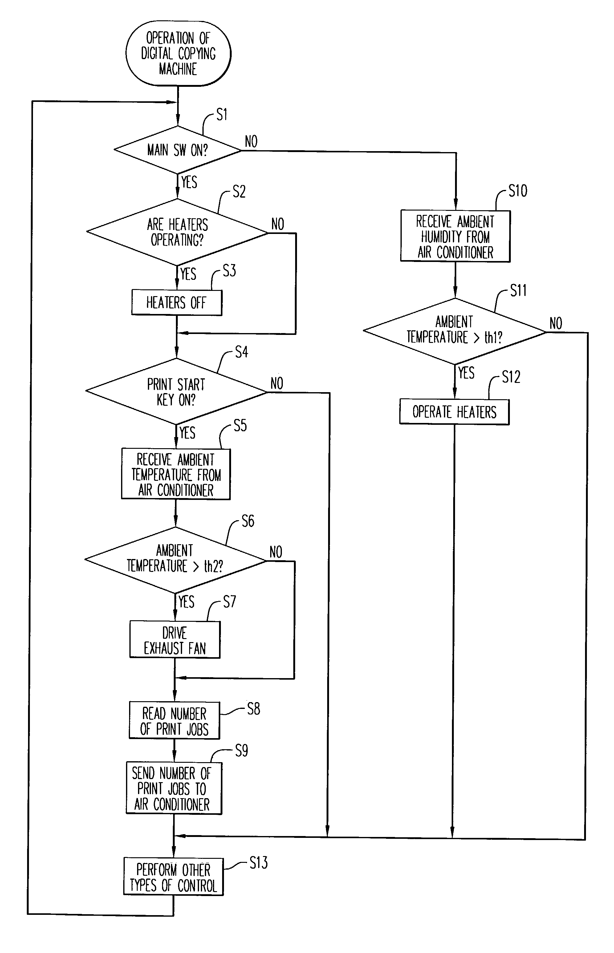
[0009]Using this construction, the image forming apparatus reads the operation information comprising the number of print jobs or the like being processed by the apparatus, for example, and transmits the operation information to the air conditioner. The air conditioner then adjusts the ambient temperature and / or humidity in the room in which the image forming apparatus is installed in accordance with the amount of heat that will be generated through the operation of the image forming apparatus, which is anticipated from the operation information thus received. Because the operations of the image forming apparatus and the air conditioner are coordinated in this way, the ambient temperature and humidity can be optimally adjusted by the air conditioner in accordance with the operation of the image forming apparatus.
[0011]Using this construction, the image forming apparatus receives information regarding the ambient temperature and / or humidity from the air conditioner, and controls, based on the ambient temperature and / or humidity information received, the adjusting means such as the exhaust fan, the condensation prevention heater and the moisture elimination heaters to adjust the temperature and / or moisture content inside the image forming apparatus. Since the operations of the image forming apparatus and the air conditioner can be coordinated in this way, such that the temperature and moisture content inside the image forming apparatus are adjustable in accordance with the ambient temperature and humidity detected by the air conditioner, power conservation and less noise can be achieved when utilizing the cooling function, the moisture eliminating function or the condensation preventing function of the image forming apparatus.
[0012]Moreover, since the temperature and / or humidity readings detected by the sensors included in the air conditioner are used, it is not necessary to separately equip the image forming apparatus with sensors to detect the ambient temperature and / or humidity, enabling the image forming apparatus to have a simpler construction and a lower cost.
[0014]Using this construction, since the temperature and moisture content inside the apparatus are adjusted in accordance with the ambient temperature and humidity even when the main switch is OFF, power conservation can be achieved for the image forming apparatus while at the same time providing the proper moisture content of the paper immediately after the power is turned ON and preventing the formation of condensation on the mirrors and the lenses, for example.

Problems solved by technology

However, in the past, the image forming apparatus and the air conditioner did not operate in a linked fashion, and worked independently from each other.
Consequently, the problem arises that, due to the internal heat generated when the image forming apparatus operates, if the image forming apparatus is used over a long period of time, the generated heat can affect the ambient temperature and humidity in the room, because the air conditioner does not adjust the temperature and humidity in the room in accordance with the operation status of the image forming apparatus.
Therefore, optimal adjustment of the ambient temperature and humidity in the room in accordance with the operation status of the image forming apparatus has not been achieved previously.
Consequently, where the ambient temperature is around 25° C., which is a common room temperature, the cooling means continues to provide excessive cooling, resulting in the problems of increased power consumption and noise.
These problems are not limited to the cooling function, but also occur with regard to the moisture eliminating and condensation preventing functions.

Method used


Image

  • Image forming apparatus
  • Image forming apparatus
  • Image forming apparatus

Examples


Embodiment Construction

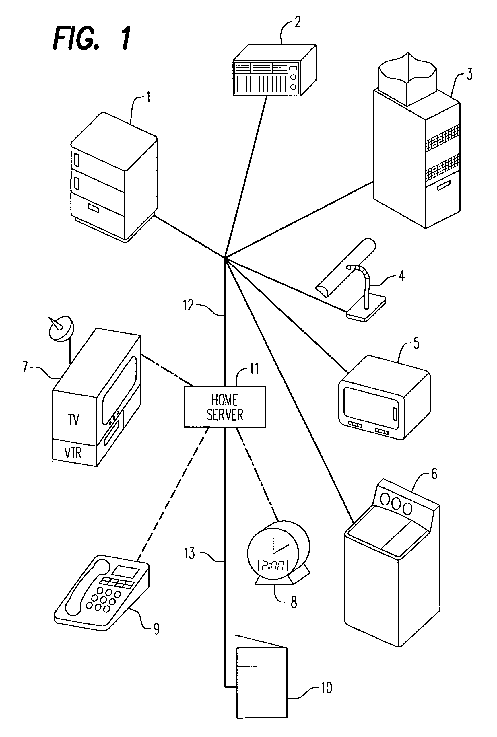
[0023]FIG. 1 is a drawing showing the overall construction of a home automation system that includes a digital copying machine, which comprises the image forming apparatus in one embodiment of the present invention.

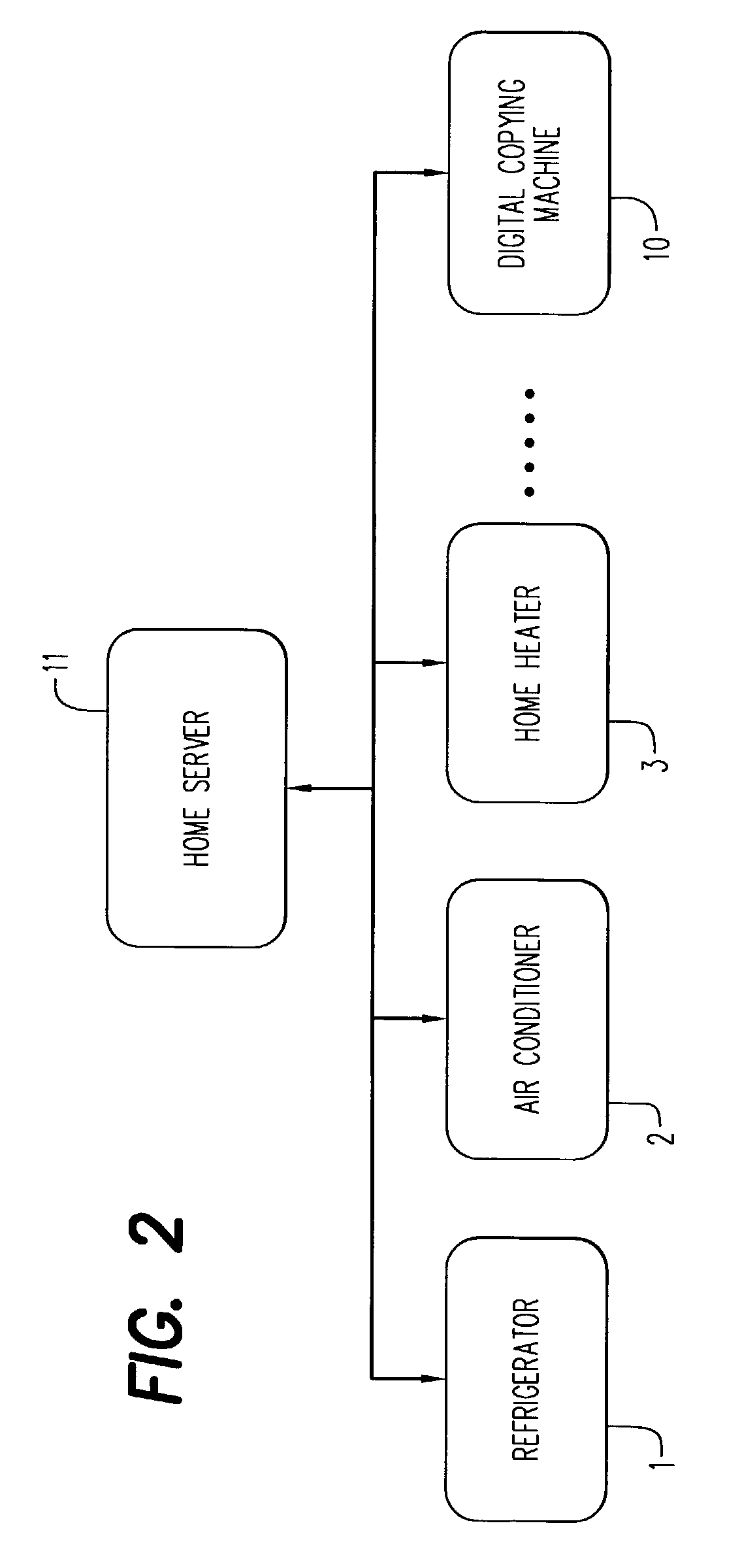
[0024]This home automation system includes a refrigerator 1, an air conditioner 2, a home heater 3, a fluorescent lamp 4, a microwave oven 5, a washing machine 6, a television receiver 7, a clock 8, a telephone 9, a digital copying machine 10 and a home server 11 that performs overall control of each of these apparatuses.

[0025]The refrigerator 1, the air conditioner 2, the home heater 3, the fluorescent lamp 4, the microwave oven 5 and the washing machine 6 are connected to the home server 11 using an electrical cable 12 and comprise a sub-network. The television receiver 7 and the clock 8 are connected to the home server 11 using infrared lines and comprise a sub-network. The telephone 9 is wirelessly connected to the home server 11 and comprises a sub-network. The digit...


PUM


Abstract

An image forming apparatus such as a copier and an air conditioner communicate with one another in a network. The air conditioner provides information regarding ambient temperature and / or humidity to the image forming apparatus. Based upon this information, the image forming apparatus selectively activates systems within the apparatus that regulate its internal temperature and humidity levels, to thereby achieve power savings. The image forming apparatus provides information regarding its operation state to the air conditioner. The air conditioner uses this information to adjust its heating or cooling operations to compensate for the heat generated by the image forming apparatus when it is operating.

Description

[0001]This disclosure is based upon Japanese Patent Application No. 2001-382196, filed Dec. 14, 2001, the contents of which are incorporated herein by reference.FIELD OF THE INVENTION[0002]The present invention relates to an image forming apparatus, such as a digital copying machine or a printer, that is capable of working in coordination with an air conditioner that adjusts the ambient temperature and / or humidity of a room.BACKGROUND OF THE INVENTION[0003]As the use of air conditioners and other environmental control devices becomes commonplace, image forming apparatuses such as copying machines or printers are increasingly being installed in air-conditioned rooms in offices and homes.[0004]However, in the past, the image forming apparatus and the air conditioner did not operate in a linked fashion, and worked independently from each other. Consequently, the problem arises that, due to the internal heat generated when the image forming apparatus operates, if the image forming appar...

Claims


Application Information

Patent Timeline
IPC IPC(8): G06F15/16G03G15/00G03G21/20B41J29/377F24F11/02G06F3/12H04N1/00
CPCH04N1/00127H04N1/00978H04N1/00986H04N1/00992G03G21/203H04N2201/001
Inventor IGUCHI, YUKINOBUMAEKAWA, FUMIO
Owner MINOLTA CO LTD
Learn More