Flowmeter

Active Publication Date: 2019-05-02
TOFLO CORP
View PDF0 Cites 3 Cited by
  • Summary
  • Abstract
  • Description
  • Claims
  • Application Information

AI Technical Summary

Benefits of technology

[0014]According to the flowmeter of the present invention, since the coil case and the amplifier case are connected via the case made of resin, the direct transfer of the temperature from the body to the amplifier circuit board can be prevented. Further, since the insulation material is provided inside the case, no convection of air occurs in the space inside the case, and when a high temperature fluid flows through the flow path, the heat transfer to the amplifier circuit board can be prevented, and on the other hand, when a low temperature fluid flows through the flow path, condensation of the amplifier circuit board can be prevented.
[0015]According to the flowmeter of the present invention, since the metallic oil case is interposed at the connection portion of the case and the body, the coil case acts as a buffering material to prevent damage to the case due to heat shock. Furthermore, since the ground conducting wire is conducted to the body via the coil case, the detection signal of the coil is less likely to be affected by disturbance noise, and since the inside of the coil case is filled with the heat-resistant material, even if the body condenses due to a low temperature fluid, the ground conducting wire will not get rusted and no contact failure will occur, so that the pickup coil can be operated accurately for a long period of time

Problems solved by technology

However, since the heat insulating air chamber is provided between the measuring chamber and the magnetic sensor, the air in the chamber gets heated, causing convection.
Due to this convection, heat is transmitted to the metallic side wall of the sensor accommodation chamber accommodating the magnetic sensor, which causes a problem that the temperature of the magnetic sensor inside the sensor accommodation chamber ris

Method used


Image

  • Flowmeter
  • Flowmeter
  • Flowmeter

Examples


Example

[0026]Next, embodiments for carrying out the present invention will be described with reference to the drawings.

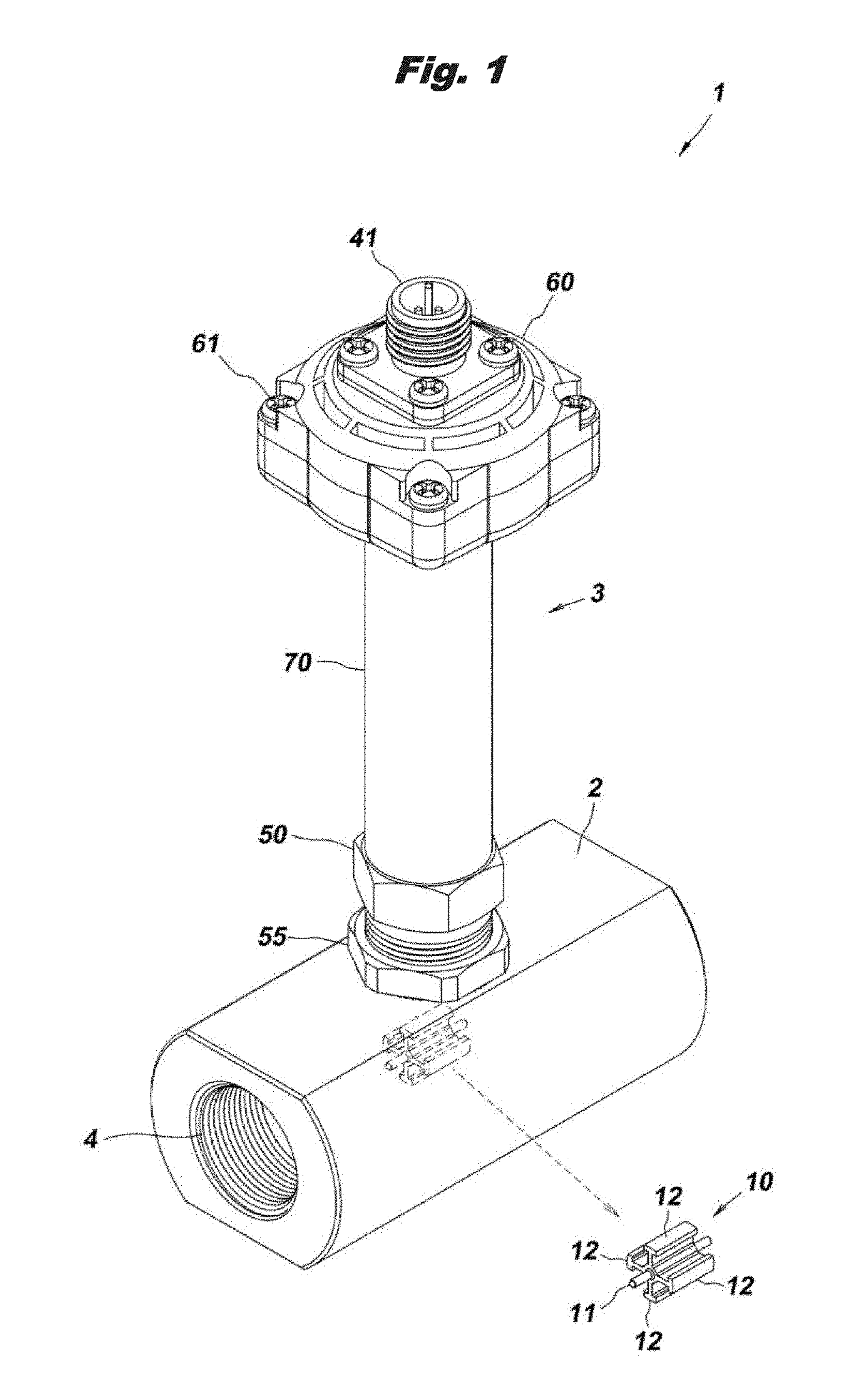
[0027]As shown in FIG. 1, the flowmeter 1 of this embodiment is an axial flow impeller (turbine) type flowmeter configured to measure a flow rate of a fluid based on the number of rotations of an impeller 10 built in the body 2, and a sensor-amplifier integrated type flowmeter in which a sensor unit 3 composed of a magnetic sensor for detecting the number of rotations of the impeller 10 and an amplifier are attached to the body 2. As an application of the flowmeter 1, for example, it can be used for measuring a flow rate of a fluorine-based inert fluid by attaching to a horizontal pipe of a temperature control chiller of a semiconductor manufacturing equipment. Further, the flow rate can be measured in a wide range of temperature between the fluid temperatures of at least from a very low temperature of −80° C. to a high temperature of +200° C.
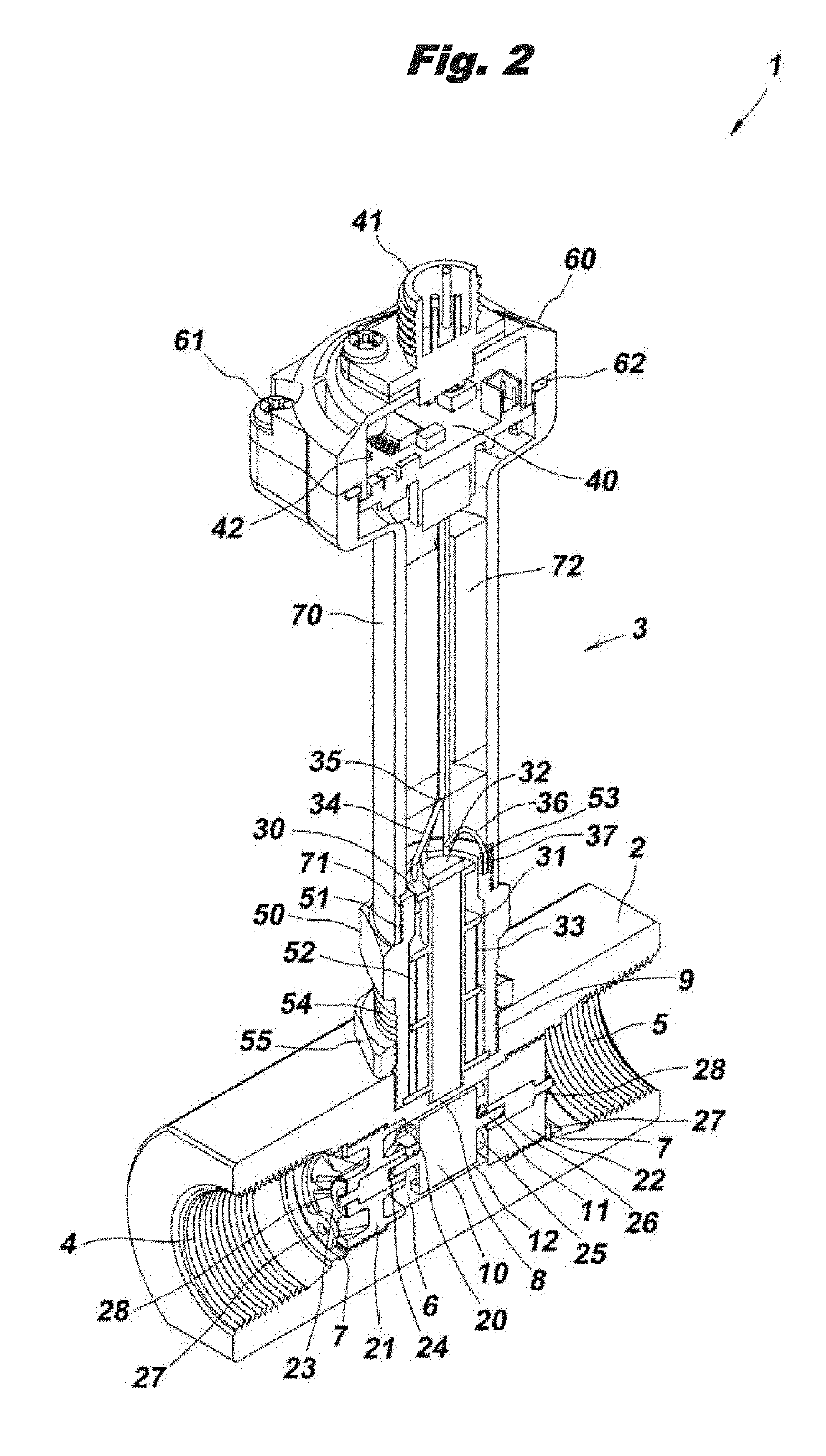
[0028]As shown in FIG. 2 and F...


PUM


Abstract

A flowmeter includes a metallic body that has a flow path therein, an impeller that is rotatably supported in the flow path inside the body, a pickup coil that is configured to detect a number of rotations of the impeller, the pickup coil being disposed outside the body, a coil case that is made of metal, and accommodates the pickup coil, an amplifier circuit board that is configured to amplify a detection signal of the pickup coil, and an amplifier case that is made of resin, and accommodates the amplifier circuit board. The coil case and the amplifier case are connected via a resin case that is made of resin and includes an insulation material therein.

Description

TECHNICAL FIELD[0001]The present invention relates to an impeller-type flowmeter for measuring a flow rate of a fluid based on the number of rotations of an impeller, and particularly to a structure of the impeller-type flowmeter capable of coping with an abrupt temperature change of a fluid.BACKGROUND[0002]Conventionally, as a flowmeter of this kind, for example, an impeller-type flowmeter described in the following Patent Document 1 is known. The flowmeter is for detecting a rotation of an impeller with a magnetic sensor, and between a measuring chamber in which the impeller is disposed and the magnetic sensor, a heat insulating plate made of synthetic resin is arranged and a heat insulating air chamber is formed. Also, at the portion constituting the outer peripheral wall of the heat insulating air chamber, a heat radiating vent hole which allows air to come in and out between the heat radiation air chamber and the outside and a heat radiation fin are provided (see FIG. 1 of Pate...

Claims


Application Information

Patent Timeline
IPC IPC(8): G01F1/115
CPCG01F1/115G01F1/10G01F15/02G01F15/14
Inventor KAWAMOTO, TAKAHIROSEKINE, TETSUAKITOBIMATSU, SHINJI
Owner TOFLO CORP
Why Eureka
Try Eureka