Gerotor apparatus for a quasi-isothermal brayton cycle engine

a cycle engine and quasi-isothermal technology, applied in the direction of machines/engines, rotary/oscillating piston pump components, liquid fuel engines, etc., can solve the problems of difficult to achieve perfect erickson cycle, low power density, difficult to achieve internal combustion, etc., to achieve simple gas flow paths, reduce power consumption, and reduce the effect of bearing load

Inactive Publication Date: 2006-03-07
STARROTOR CORPORATION +1
View PDF25 Cites 24 Cited by
  • Summary
  • Abstract
  • Description
  • Claims
  • Application Information

AI Technical Summary

Benefits of technology

[0020]Embodiments of the invention provide a number of technical advantages. Embodiments of the invention may include all, some, or none of these advantages. One technical advantage is a more compact and lightweight Brayton cycle engine having simpler gas flow paths, less loads on bearings, and lower power consumption. Some embodiments have fewer parts then previous Brayton cycle engines. Another advantage is that some embodiments of the invention introduce a simpler method for regulating leakage from gaps. An additional advantage is that the oil path is completely separated from the high-pressure gas preventing heat transfer from the gas to the oil. A further advantage is that precision alignment between the inner and outer gerotors may be achieved through a single part (e.g., a rigid shaft). A still further advantage is that drive mechanisms disclosed herein have small backlash and low wear.

Problems solved by technology

The Otto Cycle engine is an inexpensive, internal combustion, low-compression engine with a fairly low efficiency.
In practice, a perfect Erickson cycle is difficult to achieve because isothermal expansion and compression are not readily attained in large, industrial equipment.
It features low power density, mechanical complexity, and difficult-to-achieve constant-temperature compressor and expander.
It has a higher power density than the Carnot cycle, but it is difficult to perform the heat exchange, and it is difficult to achieve constant-temperature compression and expansion.
In practice, real engines have “irreversibilities,” or losses, associated with friction and temperature / pressure gradients.
These devices are generally suitable for aviation in which aircraft operate at fairly constant speeds; they are generally not suitable for most transportation applications, such as automobiles, buses, trucks, and trains, that must operate over widely varying speeds.
Further, the Otto and Diesel cycle engines lose efficiency because they do not completely expand high-pressure gases, and simply throttle the waste gases to the atmosphere.

Method used


Image

  • Gerotor apparatus for a quasi-isothermal brayton cycle engine
  • Gerotor apparatus for a quasi-isothermal brayton cycle engine
  • Gerotor apparatus for a quasi-isothermal brayton cycle engine

Examples


Embodiment Construction

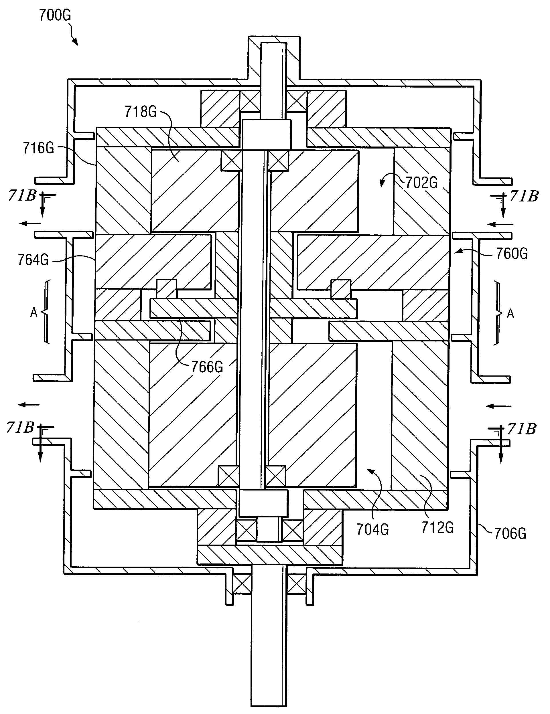
[0050]FIGS. 1 through 101 below illustrate example embodiments of a gerotor apparatus within the teachings of the present invention. Generally, the following detailed description describes gerotor apparatuses as being used in the context of a gerotor compressor; however, the following gerotor apparatuses may function equally as well as gerotor expanders or other suitable gerotor apparatuses. In addition, the present invention contemplates that the gerotor apparatuses described below may be utilized in any suitable application; however, the gerotor apparatuses described below are particularly suitable for a quasi-isothermal Brayton cycle engine, such as the one described in U.S. Pat. No. 6,336,317 B1 (“the '317 patent”) issued Jan. 8, 2002, and assigned to the Texas A&M University System. The '317 patent, which is herein incorporated by reference, describes the general operation of a gerotor compressor and / or a gerotor expander. Hence, the operation of the gerotor apparatuses describ...


PUM


Abstract

According to one embodiment of the invention, a gerotor apparatus includes an outer gerotor having an outer gerotor chamber, an inner gerotor, at least a portion of which is disposed within the outer gerotor chamber, and a synchronizing apparatus operable to control the rotation of the inner gerotor relative to the outer gerotor. The inner gerotor includes one or more entrance passages operable to communicate a lubricant into the outer gerotor chamber.

Description

RELATED APPLICATIONS[0001]This application claims benefit under 35 U.S.C. §119(e) of U.S. Provisional Application Ser. No. 60 / 355,636, entitled “QUASI-ISOTHERMAL BRAYTON CYCLE ENGINE,” filed Feb. 5, 2002, and U.S. Provisional Application Ser. No. 60 / 358,681, entitled “QUASI-ISOTHERMAL BRAYTON CYCLE ENGINE,” filed Feb. 21, 2002, and U.S. Provisional Application Ser. No. 60 / 397,193, entitled “QUASI-ISOTHERMAL BRAYTON CYCLE ENGINE,” filed Jul. 18, 2002.TECHNICAL FIELD OF THE INVENTION[0002]The present invention relates to a gerotor apparatus that functions as a compressor or expander. The gerotor apparatus may be applied generally to Brayton cycle engines and, more particularly, to a quasi-isothermal Brayton cycle engine.BACKGROUND OF THE INVENTION[0003]For mobile applications, such as an automobile or truck, it is generally desirable to use a heat engine that has the following characteristics: internal combustion to reduce the need for heat exchangers; complete expansion for improved ...

Claims


Application Information

Patent Timeline
Patent Type & Authority Patents(United States)
IPC IPC(8): F03C4/00F04C2/00F01C1/10F01C11/00F01C17/02F01C19/08F01C20/28F01C21/00F01C21/02F01C21/04F01C21/06F01C21/10F04C2/10F04C18/10F04C29/00
CPCF01C1/10F01C1/104F01C11/004F01C17/02F01C19/08F01C19/085F01C20/12F01C20/28F01C21/008F01C21/02F01C21/04F01C21/06F01C21/102F04C2/105F04C18/10F04C29/0085F01C1/103F04C2230/91F04C2230/601F04C2230/602F01C11/00
Inventor HOLTZAPPLE, MARK T.RABROKER, GEORGE A.BECK, THOMAS J.EHSANI, MARKWHITEACRE, MATTHEW M.ROSS, MICHAEL KYLENOYES, GARY P.
Owner STARROTOR CORPORATION
Why Eureka
Try Eureka