Wind turbine rotor

a technology for wind turbines and rotors, which is applied in the direction of wind energy generation, renewable energy generation, machines/engines, etc., can solve the problems of unsuitable modern day large wind turbine blades, joint weight too heavy to be scaled up to the size required for modern day turbines, etc., and achieves the effect of simple fixing and simple lifting of individual blades

Inactive Publication Date: 2010-04-08
BLADE DYNAMICS LTD
View PDF15 Cites 28 Cited by
  • Summary
  • Abstract
  • Description
  • Claims
  • Application Information

AI Technical Summary

Benefits of technology

[0021]This means that instead of one large bearing taking the full bending moment of the blade perpendicular to the plane of rotation, there are now two smaller bearings taking the bending moment out of the blade within the plane of rotation of each bearing. Not only does this provide a load situation which is more suitable for a bearing (in plane of bearing rotation as opposed to perpendicular to plane of bearing rotation) but also allows the loads on each bearing to be further reduced by increasing the separation of the bearings. Therefore the load on each bearing is reduced and is in a direction that the bearing is more able to support, leading to a smaller and more reliable bearing arrangement. Ultimately this leads to reduced bearing cost and increased reliability when compared to the prior art. It also allows the means by which the blade is fixed to the hub to be simplified reducing or eliminating the need for a thick root end to accommodate the array of bolts.
[0024]By contrast, in the conventional design, the blade abuts against the distal end of the bearing such that there is no overlap. As soon as the blade begins to overlap with the bearings, the bending loads on the blade begin to reduce as they are taken up by the bearings. This facilitates the fixing of the blade to the hub as whatever fixing is used is required to bear less load.
[0025]Preferably, each spar is fixed to the hub at a location radially inwards of the proximal end of the proximal bearing. This maximises the advantage referred to above as, beyond the proximal end of the proximal bearing, the bending moments on the blade have reduced to zero. The fixing between the blade and the hub is then only required to support the axial force on the blade (FAxial) caused by the gravitational and centrifugal loading. This fixing can therefore be greatly simplified as compared to the multiple bolts and steel inserts of the prior art.
[0027]The rotor hub can be made predominantly from composite material. The only metallic pieces may be the pitch bearings and the bearings and supports for the rotor shaft attachment. The section of hub the between the two bearings essentially replaces what was the ‘root structure’ of PCT / GB2008 / 002571. In this section the root has predominantly more unidirectional material on the faces which are taking the highest blade loads (typically the flapwise parts) and predominantly more multiaxial material on the faces which are taking the highest shear loads (typically the edgewise parts). This variation in the laminate structure can be replicated in this section of the hub allowing for optimal use and orientation of different fibre types and arrangements and this is now a preferred route in this case. Also, the need for metallic inserts can be avoided by moving the fixing proximally of the bearings, thereby removing the need make the blade thicker at the root end. These considerations alone provide a reduction of around 25% of the hub and root mass.
[0028]Preferably, the spar and bearings are configured to allow each blade to be slid into and out of the hub along the respective axis of rotation of the blade. This provides a simple way of assembling the blades to the hub.
[0030]The method is an improvement on the prior art as it allows for a much simpler fixing between the blade and the hub, particularly if the spar is fixed to the hub radially inwards of the proximal end of the proximal bearing and ideally using the pin.

Problems solved by technology

The mounting is suitable for a windmill in the 1970s (which would have had a rotor diameter of less than 20 m), but is not suitable for a modern day wind turbine blade, the blade length of which could be in order of magnitude greater than the blade contemplated by U.S. Pat. No. 4,029,434.
The manner in which the bearing is connected makes it unsuitable for a modern day large wind turbine.
In particular, the requirement for two arrays of bolted joints, one at either end of the bearing would make the joint too heavy to be scaled up to the size required for a modern day turbine.
Its use in a modern large scale wind turbine blade would only make the problems referred to below with regard to the plurality of bolts worse.
For off-shore installations, a large tower head mass is one of the significant problems with cost-effective deployment of the technology in this environment.
The inserts 11 are very difficult to produce with a high degree of repeatability.
In addition, the inserts are typically metallic and can cause problems due to differences in thermal expansion coefficient relative to the composite root structure, as well as difficulties in bond adhesion to the steel insert.
This leads to the root end of the blade being heavy.
This means that the bearings are large diameter, expensive and heavy components in order to be able to cope with the large and varied forces.
A number of pitch bearings have failed in use under these loads.
The large diameter required for the pitch bearing for the reasons set out above means that the root end of the blade needs to be made thicker (larger diameter) than is desirable for aerodynamic performance, thereby decreasing the efficiency of the blade.
This is a time-consuming process which must be carried out with great care if problems are to be avoided.

Method used


Image

  • Wind turbine rotor
  • Wind turbine rotor
  • Wind turbine rotor

Examples


Embodiment Construction

[0045]Throughout this specification, the term distal refers to a part towards the radially outermost edge of the rotor (i.e., towards the tips of the blade), while the term proximal refers to the radially innermost part of the rotor (i.e., towards the centre of the hub).

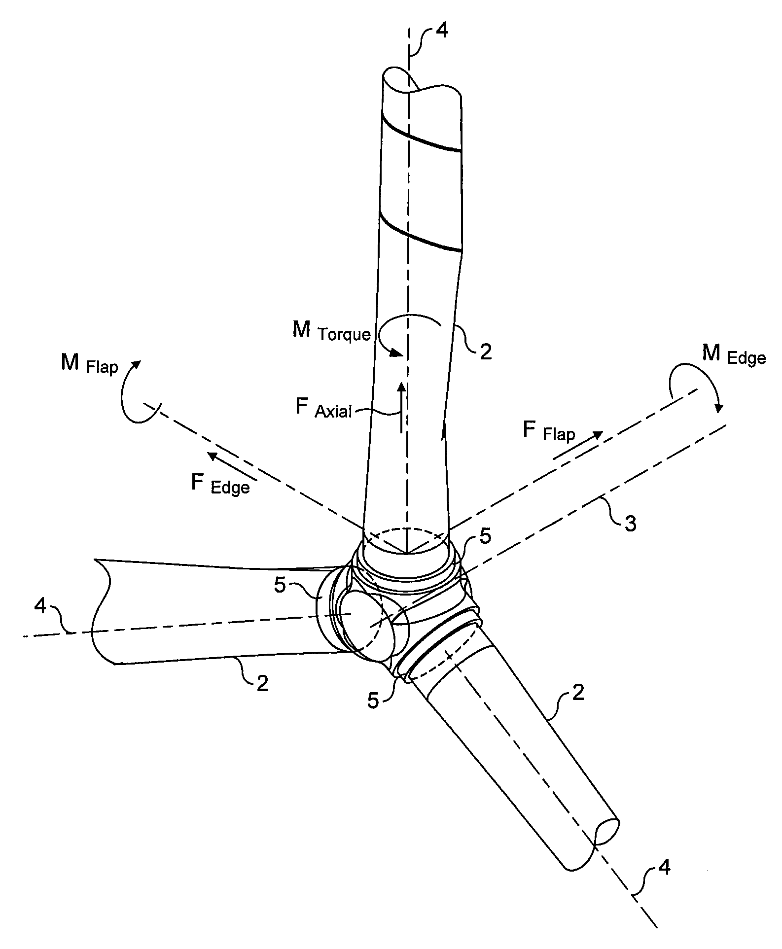
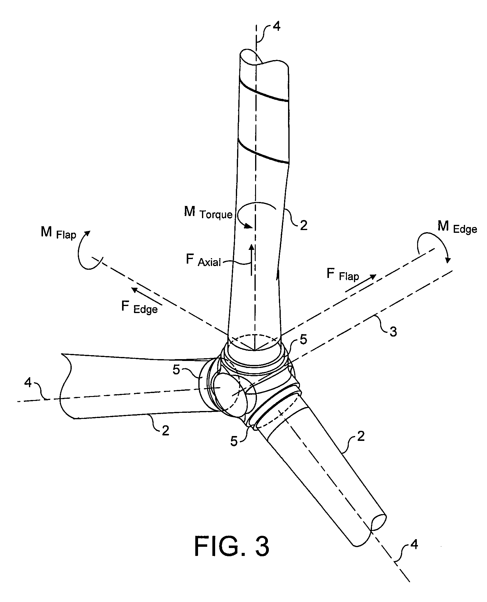
[0046]The various forces acting on the blade are shown in FIG. 3 which is described in the introduction and will therefore not repeated here.

[0047]The rotor comprises a hub 20 to which three blades 21 (only one of which is shown in FIG. 4) are attached. The blade is shown is attached in a first port 22 and it will be readily understood that the two remaining blades are attached in identical fashion at remaining ports 23, 24.

[0048]The rotor is rotatable about the main axis 25. Each of the blades is rotatable about a pitch axis 26 by a respective pitch motor (not shown) in order to optimise the angle of the blade for the prevailing wind conditions.

[0049]Each blade comprises an outer shell 27 which extends to the tip of...


PUM

PropertyMeasurementUnit
diameteraaaaaaaaaa
diameteraaaaaaaaaa
lengthaaaaaaaaaa

Abstract

A wind turbine rotor comprising a hub and a plurality of blades. The hub comprises a plurality of sites, each having a pair of spaced apart annular bearings for receiving a respective wind turbine blade. Each blade has a spar extending along a substantial portion of the length of the blade and protrudes from the proximal end of the blade. The spar protrudes into and is rotatably received within the respective spaced apart bearings and is fixed to the hub.

Description

CROSS-REFERENCE TO RELATED APPLICATIONS[0001]This application claims benefit of British patent application number 0818466.5, filed Oct. 8, 2008, which is herein incorporated by reference.BACKGROUND OF THE INVENTION[0002]1. Field of the Invention[0003]The present invention relates to a hub for a wind turbine.[0004]2. Description of the Related Art[0005]Current large-scale horizontal axis wind turbines have tower head weights (including the rotor, nacelle and drive train) of the order of 120 to 200 metric tonnes. There is an increasing trend for larger diameter turbines and the weight of the tower head is increasing approximately as the cube of the diameter of the turbine. The rotor itself (made up of the hub and blades) accounts for roughly 30% of the tower head weight. Approximately 60% of this is attributed to the blades while 40% is attributable to the hub.[0006]U.S. Pat. No. 4,029,434 discloses the blade mounting for a windmill. The root of the blade extends into the hub where it...

Claims


Application Information

Patent Timeline
Patent Type & Authority Applications(United States)
IPC IPC(8): F03D1/06F03D3/06B23P15/04
CPCF03D1/0658F03D3/062F03D3/064Y10T29/49316Y02E10/721Y02E10/74F03D11/0008F03D80/70Y02E10/72
Inventor WHILEY, DAVID ANTHONYHAYDEN, PAUL TREVOR
Owner BLADE DYNAMICS LTD
Why Eureka
Try Eureka