Gas turbine engine with seal assembly

a technology of seal assembly and gas turbine engine, which is applied in the direction of positive displacement liquid engine, liquid fuel engine, piston pump, etc., can solve the problems of thermal buckling and reduce the life span, and achieve the effect of extending the life of the seal assembly and the engine, and reducing thermal stress damag

Inactive Publication Date: 2006-01-19
HANWHA POWER SYST CO LTD
View PDF5 Cites 26 Cited by
  • Summary
  • Abstract
  • Description
  • Claims
  • Application Information

AI Technical Summary

Benefits of technology

[0010] The present invention is directed to a seal assembly for a gas turbine engine, and a gas turbine incorporating the seal assembly therein. The seal assembly includes a seal member and a heat shield member configured to restrain the fluid flow between a compressor section and a turbine section and also to limit heat transfer from the turbine section to the compressor section. The seal assembly can also resist thermal stresses on the heat shield member which exposes to the hot combustion gases flowing from the turbine section.
[0015] According to the present invention, the heat shield member and the sealing assembly can reduce damage from thermal stresses in the area contacting the high-temperature gases flowing from the turbine section, and can extend the life of the seal assembly and the engine.

Problems solved by technology

However, since a portion of the heat shield member contacting the high-temperature combustion gases has a flat plate shape, a serious thermal buckling can be occurred from a prolonged use of the engine, particularly, by repeatedly exposing to a sharp change in the temperature during the transition operation cycles of the gas turbine engine, thus reducing the life span thereof.

Method used


Image

  • Gas turbine engine with seal assembly
  • Gas turbine engine with seal assembly
  • Gas turbine engine with seal assembly

Examples


Embodiment Construction

[0024] The present invention will now be described more fully with reference to the accompanying drawings, in which exemplary embodiments of the invention are shown.

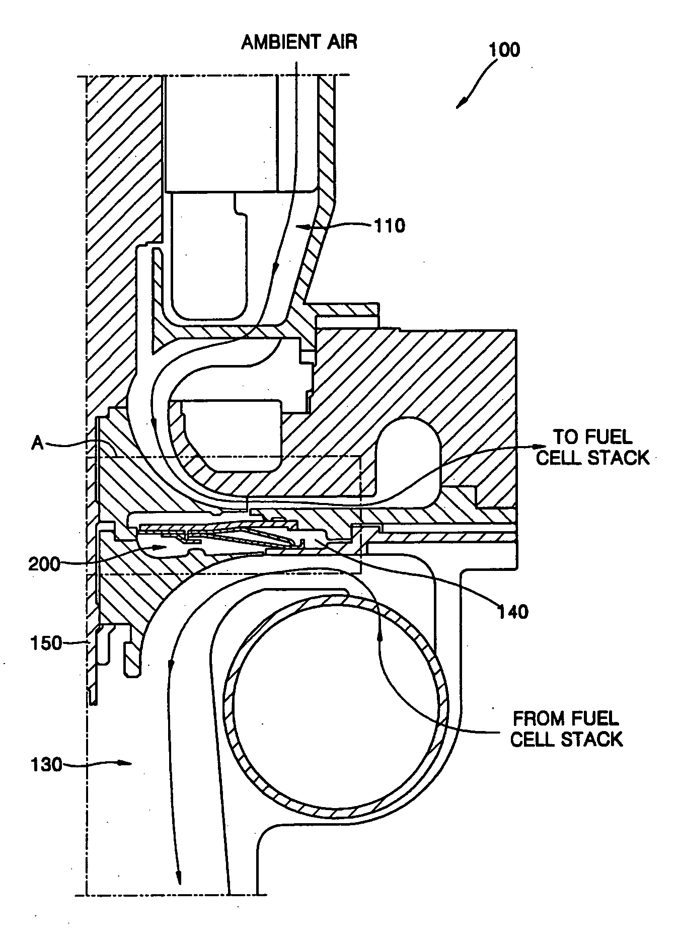
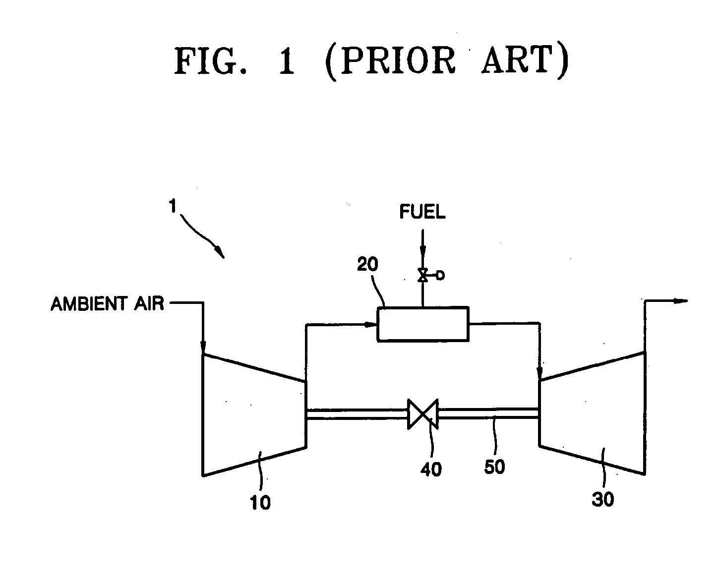
[0025] According to one embodiment of the invention, a turbo charger 100 is described herein as one example of a gas turbine engine, which incorporates the seal assembly of the invention. However, the present invention is not limited to the turbo charge, and generally applicable to any suitable type of gas turbine engines.

[0026] Referring to FIG. 3, the turbo charger 100 includes a seal assembly 200 constructed according to the principles of the invention. The turbo charger 100 includes a turbine section 130 and a compressor section 110. The turbine section 130 drives a rotating shaft by high-temperature compressed gases. The compressor section 110 is coaxially coupled to the turbine section 130 with a shaft 150, and compresses ambient air by the driving force of the turbine section 130. The compressor section 110 and ...


PUM


Abstract

A gas turbine engine includes an interstage seal assembly positioned in a plenum between the compressor section and turbine section. The seal assembly includes an annular seal member positioned in the plenum adjacent to the compressor section for restraining a fluid flow between the compressor section and the turbine section, and an annular heat shield member positioned in the plenum adjacent to the turbine section for limiting heat transfer from the turbine section to the compressor section. The annular heat shield member includes a plurality of slots formed on a surface of the heat shield member in a radial direction of the annular heat shield member.

Description

[0001] This application claims the priority of Korean Patent Application No. 2004-55481, filed on Jul. 16, 2004, in the Korean Intellectual Property Office, the disclosure of which is incorporated herein by reference in its entirety. BACKGROUND OF THE INVENTION [0002] 1. Field of the Invention [0003] The present invention relates to a gas turbine engine with a seal assembly, and more particularly, to a gas turbine engine having an interstage seal assembly which includes a heat shield member for restraining heat transfer from the high-temperature turbine section to the low-temperature compressor section of the engine and a seal member for limiting the fluid flow between the compressor section and the turbine section. [0004] 2. Description of the Related Art [0005] A gas turbine engine refers typically to a type of turbine engine that operates in a Brayton cycle, one of the ideal and basic thermodynamic cycles, and continuously obtains power through compression and subsequent expansio...

Claims


Application Information

Patent Timeline
Patent Type & Authority Applications(United States)
IPC IPC(8): F02C7/00
CPCF01D11/003F02C3/05F01D11/005F02C7/24F02C7/28
Inventor KIM, KYUNG-HEUI
Owner HANWHA POWER SYST CO LTD
Why Eureka
Try Eureka