Extruder

A technology of extruder and hopper, which is applied in the field of plastic processing machinery and equipment, can solve the problems of material accumulation on the screen, and the bouncing effect is not obvious, so as to avoid waste and structure blockage and ensure the quality of extrusion molding

Pending Publication Date: 2018-11-13
YANCHENG SHENYUAN PLASTIC
View PDF1 Cites 4 Cited by
  • Summary
  • Abstract
  • Description
  • Claims
  • Application Information

AI Technical Summary

Problems solved by technology

[0005] In this invention, the middle part of the screen is an elastic screen made of elastic material, so that it can bounce due to elasticity during work to achieve a vibration effect; The bouncing effect, the bouncing effect is not obvious, and the material cannot be filtered well, which may cause the material to accumulate on the screen.

Method used


Image

  • Extruder
  • Extruder
  • Extruder

Examples


Embodiment 1

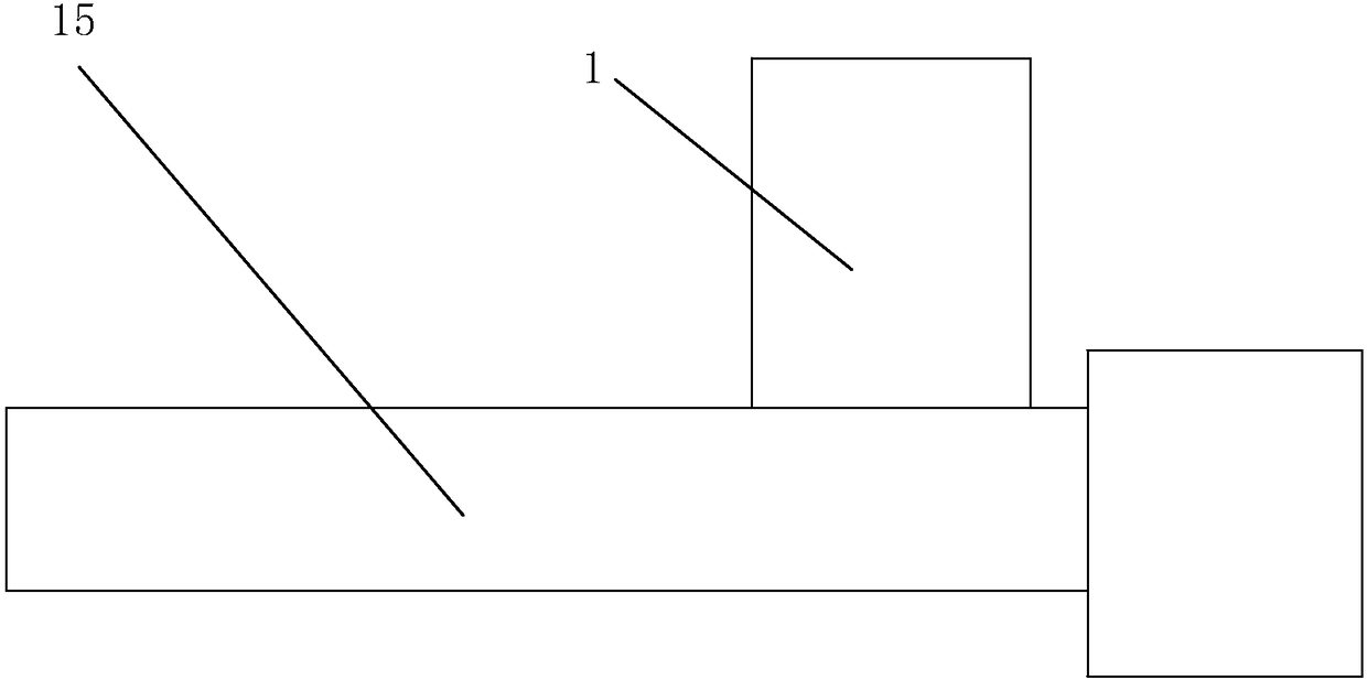
[0040] Embodiment 1: a kind of extruder, such as figure 1 As shown, it mainly includes a hopper 1 for materials to enter. The lower end of the hopper 1 is connected to the barrel 15. A transmission screw is arranged in the barrel 15. The material is thrown into the hopper 1 through the upper end of the hopper 1 and enters the barrel 15. It falls on the transmission screw, and is plasticized into a uniform melt during the transmission process of the transmission screw, and under the pressure established in this process, it is continuously extruded by the screw head to complete the extrusion of the material. .

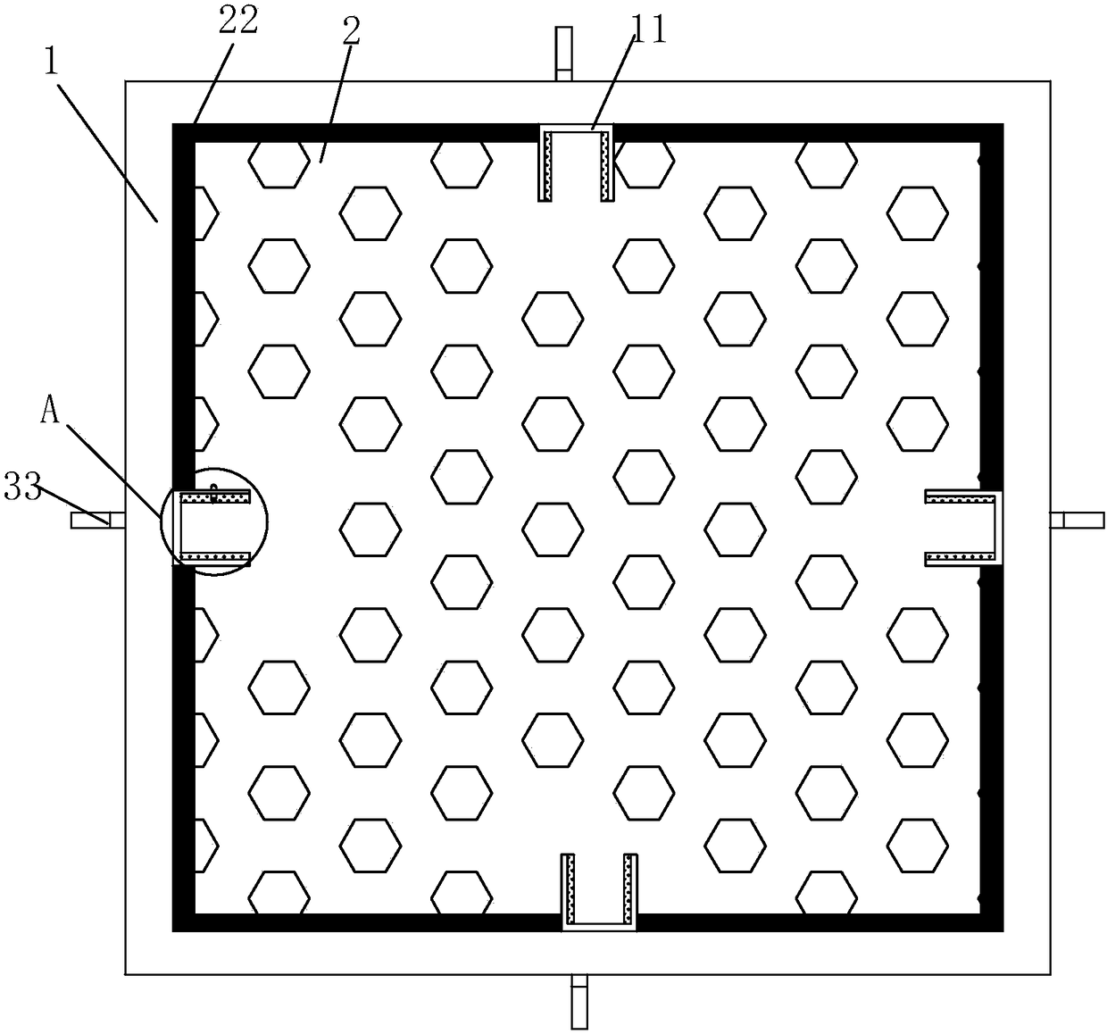
[0041] Such as figure 2 and 4 As shown, the cross section of the inner hole of the hopper 1 is in a square shape, and track grooves 16 are arranged on the four surfaces of the inner wall of the hopper 1, and supports 11 are slidingly connected in the track grooves 16, between the supports 11 Symmetrical in pairs; each support 11 is provided with a storage slot 111, t...

specific Embodiment approach

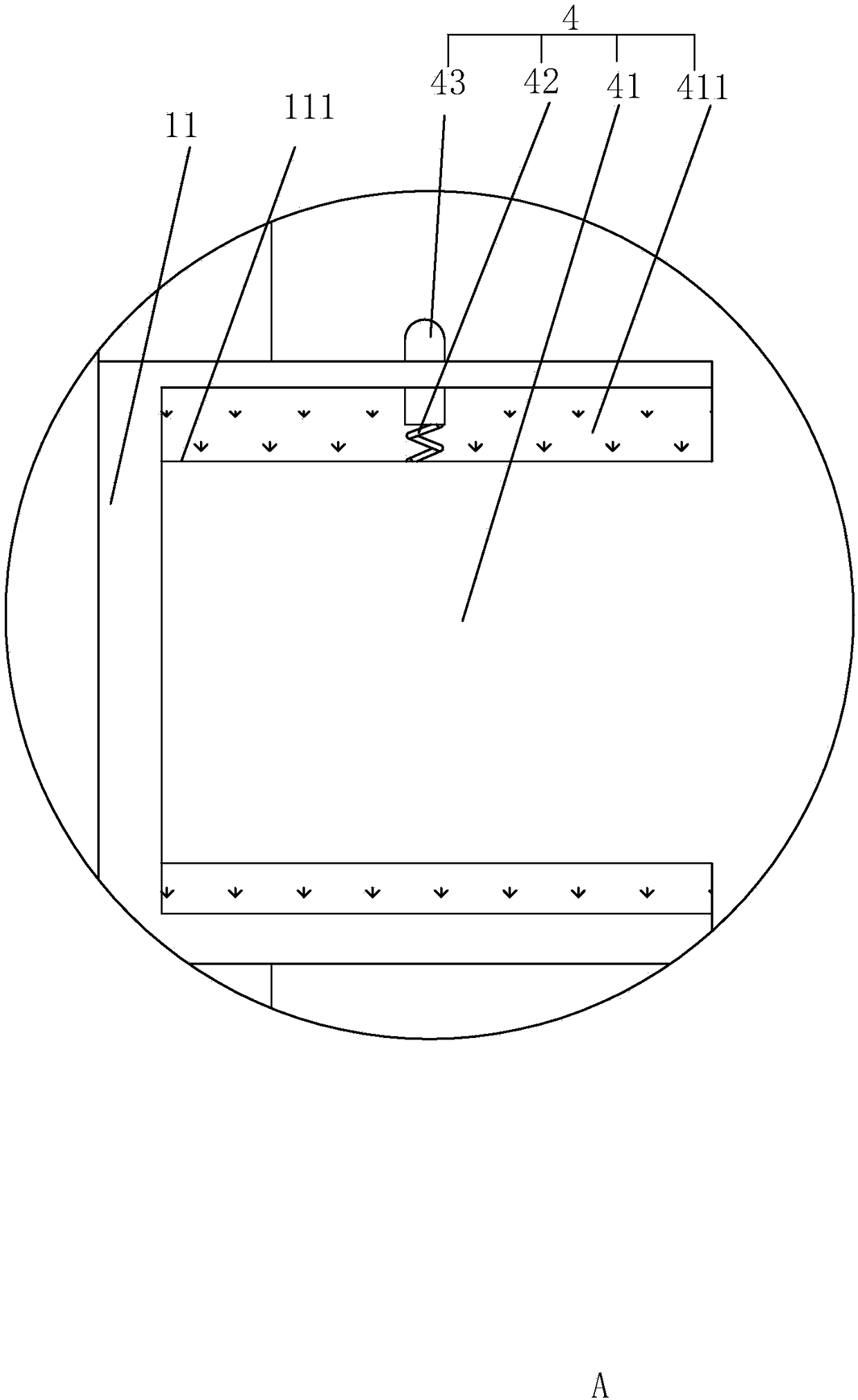
[0045] Specific implementation: before the extruder works, the sieve plate 2 needs to be installed in the extruder, that is, the sieve plate 2 is mounted on the support 11, and each extension column 41 of the sieve plate 2 is respectively embedded When the extension column 41 with the limiting column 43 is completely embedded in the storage slot 111, the limiting column 43 will firstly interfere with the inner wall of the storage slot 111, and under the action of this resistance, the compression The spring 42 is fully compressed. When the extension column 41 is fully embedded in the storage slot 111, the limiting column 43 slides along the inner side wall of the storage slot 111 to the through hole 44. At this time, the limiting column 43 is embedded in the through hole 44. The inside communicates with the outside, and at the same time, the compression spring 42 resumes its deformation. At this time, the locking of the extension column 41 in the storage slot 111 can be realized...

Embodiment 2

[0052] Embodiment 2: An extruder, the difference from Embodiment 1 is that during the process of feeding materials into the hopper 1 through the upper opening of the hopper 1, some materials will fall on the support 11 to form a The accumulation on the seat 11 will cause material waste at this time. In order to avoid this phenomenon, the upper end of the support 11 on the inner wall of the hopper 1 is provided with a deflector 14 to prevent the material from falling into the support 11. Such as Figure 6 and 7 As shown, the deflector 14 is adjusted in the hopper 1 through the adjustment device 5, so as to realize the diversion of the material and prevent the material from falling and accumulating on the support 11. At the same time, the deflector 14 can also be controlled to let out A space for the sieve plate 2 to be taken out from the hopper 1 smoothly.

[0053] Such as Figure 6 and 7 As shown, the adjusting device 5 includes working grooves 51 arranged on the inner wal...


PUM


Abstract

The invention discloses an extruder. The extruder comprises a hopper; multiple brackets for erecting screen plates are arranged on the inner wall of the hopper; the brackets are slidingly connected tothe inner wall of the hopper; connecting blocks are fixedly arranged on the inner wall of the hopper under the brackets; working springs are fixed at the bottoms of the brackets; the ends, far from the brackets, of the working springs are fixedly connected with the connecting blocks; and lifting devices for controlling the brackets to slide up and down in the hopper are arranged at the bottom ofthe connecting blocks. The extruder can filter impurities in materials, guarantees the extrusion molding quality of the materials, prevents the wear of screws, extrusion cylinders and the like, and can control screen plates to achieve a bounce effect in a working state to prevent the materials from accumulating on the surfaces of the screen plates and to enable the materials to smoothly enter a machine cylinder through the screen plates.

Description

technical field [0001] The invention relates to the field of plastic processing machinery and equipment, in particular to an extruder. Background technique [0002] The host of the plastic extruder is an extruder, which consists of an extrusion system, a transmission system and a heating and cooling system. The extrusion system includes a screw, a barrel, a hopper, a die, and a mold. The plastic is plasticized through the extrusion system. The homogeneous melt is continuously extruded by the screw under the pressure established in the process. [0003] During this process, when feeding powder or granular materials into the hopper, it is inevitable that some impurities will be mixed with some raw materials that have not been crushed. If these impurities and raw materials that have not been crushed are mixed The hard impurities that flow into the extrusion barrel will not only affect the quality of the extruded product, but also cause wear to the screw, extrusion barrel, etc....

Claims


Application Information

Patent Timeline
Patent Type & Authority Applications(China)
IPC IPC(8): B29C47/10B29C31/02B29C47/58B29B13/10
CPCB29C31/02B29B13/10
Inventor 袁森吴航贺盟唐家烨柏爱华
Owner YANCHENG SHENYUAN PLASTIC
Why Eureka
Try Eureka