
Middle supporting locking mechanism and electric bicycle

A locking mechanism and technology for electric vehicles, applied in bicycle theft prevention devices, bicycle accessories, transportation and packaging, etc., can solve the problems of ineffective anti-theft, easy to be tampered with, and cumbersome installation of center support locks, etc., to achieve increased lock removal Difficulty of theft, improvement of the anti-theft effect, improvement of the effect of the anti-theft function

Pending Publication Date: 2018-11-13
ZHEJIANG LUYUAN ELECTRIC VEHICLE
View PDF9 Cites 0 Cited by
  • Summary
  • Abstract
  • Description
  • Claims
  • Application Information

AI Technical Summary

Problems solved by technology

[0002] At present, the anti-theft performance of two-wheeled vehicles such as electric vehicles and motorcycles on the market is poor. Generally, the anti-theft is prevented by means of locking the wheels. However, the above-mentioned anti-theft methods are very easy to be demolished, resulting in property losses for users.
The existing center stay locks generally have disadvantages such as inconvenient installation, poor compatibility, and easy crashes, which are not conducive to popularization and use.
The existing center support lock is generally installed on one side of the vehicle, and the purpose of locking is achieved by locking the center support. This method is easy to remove from the outside, and the anti-theft is useless
For example, in the patent application with the application number "CN201610714367.9" and the patent application with the application number "CN201420096788.6", the installation of the center stay lock is cumbersome, and the center stay lock may be completely removed or damaged

Method used


Image

  • Middle supporting locking mechanism and electric bicycle
  • Middle supporting locking mechanism and electric bicycle
  • Middle supporting locking mechanism and electric bicycle

Examples


Embodiment Construction

[0043] In order to have a clearer understanding of the above objects, features and advantages of the present invention, the present invention will be further described in detail below in conjunction with the accompanying drawings and specific embodiments. It should be noted that, in the case of no conflict, the embodiments of the present application and the features in the embodiments can be combined with each other.

[0044] In the following description, many specific details are set forth in order to fully understand the present invention. However, the present invention can also be implemented in other ways different from those described here. Therefore, the protection scope of the present invention is not limited by the specific details disclosed below. EXAMPLE LIMITATIONS.

[0045] Refer below Figure 1 to Figure 7 Some embodiments according to the invention are described.

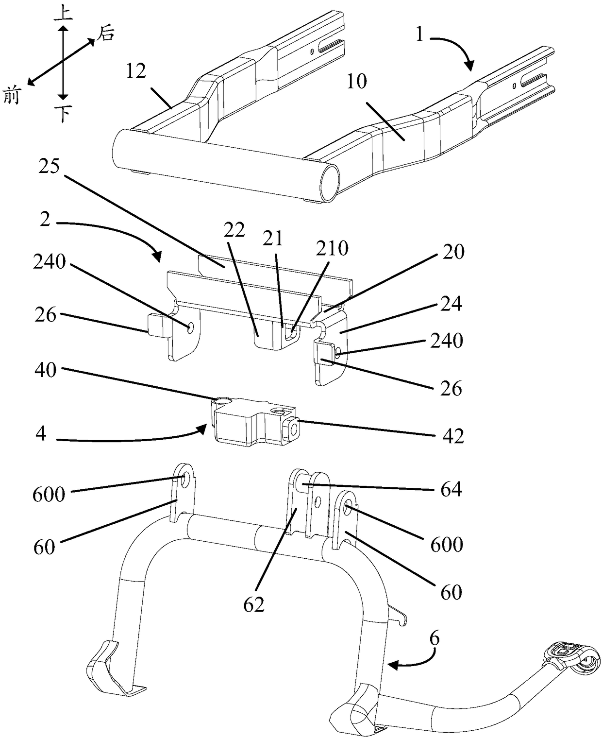
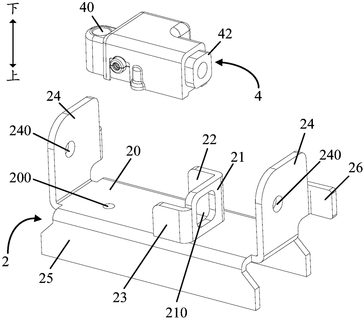
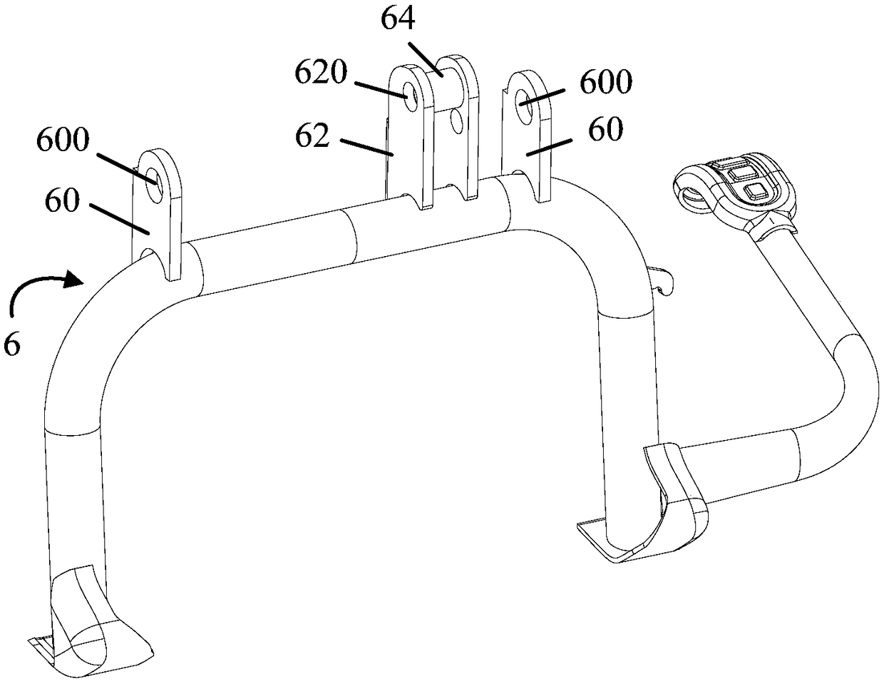
[0046] Such as Figure 1 to Figure 7 As shown, the middle support locking mechanism of an electr...


PUM


Abstract

The invention provides a middle supporting locking mechanism of an electric bicycle and the electric bicycle. The middle supporting locking mechanism comprises a rear bottom fork, a support connectedwith the rear bottom fork, a middle supporting lock arranged below the support and connected with the support, and a middle support arranged below the middle supporting lock and connected with the support through a rotatable structure, wherein a limiting space is formed between the middle support and the middle supporting lock and used for preventing the middle supporting lock from being detached.By the adoption of the technical scheme, the middle supporting lock is installed below the rear bottom fork and above the middle support through the support, the position of the middle supporting lock is hidden, the limiting space is formed by the middle supporting lock and the middle support, so that the middle supporting lock is difficult to detach, and the antitheft performance of the middle supporting lock is improved; and in addition, the middle supporting lock is in bolted connection with the support through fasteners, installation is convenient, universality is good, the position is high, and the mechanism is unlikely to be crashed.

Description

technical field [0001] The invention relates to the technical field of an anti-theft device for a middle support of an electric vehicle, in particular to a middle support locking mechanism and an electric vehicle. Background technique [0002] At present, the anti-theft performance of two-wheeled vehicles such as electric vehicles and motorcycles on the market is relatively poor. Generally, the anti-theft methods are used to prevent theft by locking the wheels. However, the above-mentioned anti-theft methods are extremely easy to be demolished, resulting in property losses for users. The existing center stay locks generally have disadvantages such as inconvenient installation, poor compatibility, and easy crash, which are unfavorable for popularization and use. The existing center stay lock is generally installed on one side of the vehicle, and the purpose of locking is achieved by locking the center support. This method is easy to remove from the outside, and the anti-theft...

Claims


Application Information

Patent Timeline
Patent Type & Authority Applications(China)
IPC IPC(8): B62H5/00B62H1/00
CPCB62H1/00B62H5/00
Inventor 倪捷王松根冯春献孙北京包健
Owner ZHEJIANG LUYUAN ELECTRIC VEHICLE
Learn More