Upper driving mechanism applicable for high-speed stacker

A technology of driving mechanism and stacker, which is applied to the stacking of objects, unstacking of objects, transportation and packaging, etc., which can solve the problems of long time required and difficulty in ensuring synchronization

Inactive Publication Date: 2018-11-13
CHANGCHUN BEIFANG INSTR EQUIP +2
View PDF6 Cites 0 Cited by
  • Summary
  • Abstract
  • Description
  • Claims
  • Application Information

AI Technical Summary

Problems solved by technology

In the past, most of the stacker drive devices were frequency conversion motors, and the synchronization was difficult to guarantee, so only the bottom drive was used.
When the maximum speed of the stacker is high, it takes a long time for the existing form of stacker to rise to the highest speed or lower from the highest speed to rest

Method used


Image

  • Upper driving mechanism applicable for high-speed stacker
  • Upper driving mechanism applicable for high-speed stacker
  • Upper driving mechanism applicable for high-speed stacker

Examples


Embodiment Construction

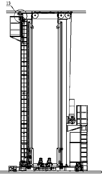
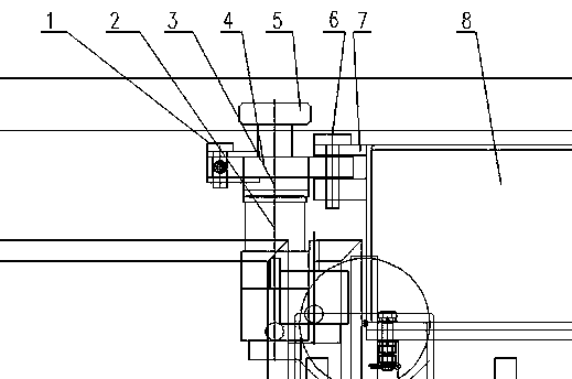
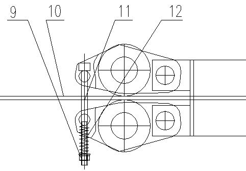
[0022] The present invention will be described in further detail below through specific embodiments and in conjunction with the accompanying drawings.

[0023] like Figure 1-3 As shown, the present invention discloses an upper driving mechanism applied to a high-speed stacker. Its structure includes a pin with a hole, a driving mechanism, a crank, a driving wheel, a pin, a mounting plate, an upper box, a lock nut, Guide rails, connecting rods and tensioning springs. Drive wheels and servo motors are mounted on the crank structure. The driving mechanism is a servo motor and a reducer, the servo motor and the reducer are installed in series, and the reducer is installed on the mounting plate. The present invention adopts the form driven by two motors, each of which is equipped with a drive wheel, and the servo motor can drive the drive wheel to rotate through the reducer. The driving wheels are made of polyurethane material to increase friction, and the two driving wheels ar...


PUM


Abstract

The invention discloses an upper driving mechanism applicable for a high-speed stacker. The upper driving mechanism comprises a driving mechanism, cranks, driving wheels, an upper box body and a guidesky rail; the driving wheels are arranged on the both sides of the guide sky rail, and installed on the cranks with the driving mechanism; the cranks are connected to the upper box body, and can be rotated around the connection position; and a pressure regulating device is arranged between the cranks, and pressure applied to the guide sky rail by the driving wheels is regulated through the pressure regulating device indirectly. According to the upper driving mechanism, the time that the speed of the stacker is increased to the maximum speed from zero speed or decreased to the zero speed fromthe maximum speed can be shortened, so that the start and stop of the stacker can be finished within the shorter time.

Description

technical field [0001] The invention relates to a mechanism for providing power or braking force when a high-speed stacker is started or stopped, so as to realize stable start and stop of the high-speed stacker, in particular to an upper driving mechanism applied to the high-speed stacker. Background technique [0002] At present, when the stacker is running at high speed, it shakes more violently when it starts or stops, and it takes a long time to wait for the equipment to stabilize, and it may even tip over. In the past, most of the stacker driving devices were variable frequency motors, and the synchronization was difficult to guarantee, so only the bottom drive was used. When the maximum speed of the stacker was high, the time required for the existing form of the stacker to rise to the highest speed or to be reduced to a standstill from the highest speed was longer. Contents of the invention [0003] In order to overcome the technical problems in the prior art, the ...

Claims


Application Information

Patent Timeline
Patent Type & Authority Applications(China)
IPC IPC(8): B65G61/00
CPCB65G61/00
Inventor 吕伟红李建民刘洋王庆旭杨鹏凌
Owner CHANGCHUN BEIFANG INSTR EQUIP
Why Eureka
Try Eureka