Needle-pushing electromagnet mechanism

An electromagnet and vertical guide technology, applied in knitting, weft knitting, textiles and papermaking, etc., can solve the problems of long operation response time and long knitting time, and achieve the effect of shortening knitting time and improving knitting efficiency

Pending Publication Date: 2018-11-13
JIANGSU JINLONG TECHNOLOGY CO LTD
View PDF7 Cites 0 Cited by
  • Summary
  • Abstract
  • Description
  • Claims
  • Application Information

AI Technical Summary

Problems solved by technology

[0002] The existing push needle mechanism of the flat knitting machine, which holds the guide rail through the magnet, and then drives the drive of the push needle cam. In actual use, the position of the magnet needs to be reset. long weaving time

Method used


Image

  • Needle-pushing electromagnet mechanism
  • Needle-pushing electromagnet mechanism

Examples


Embodiment Construction

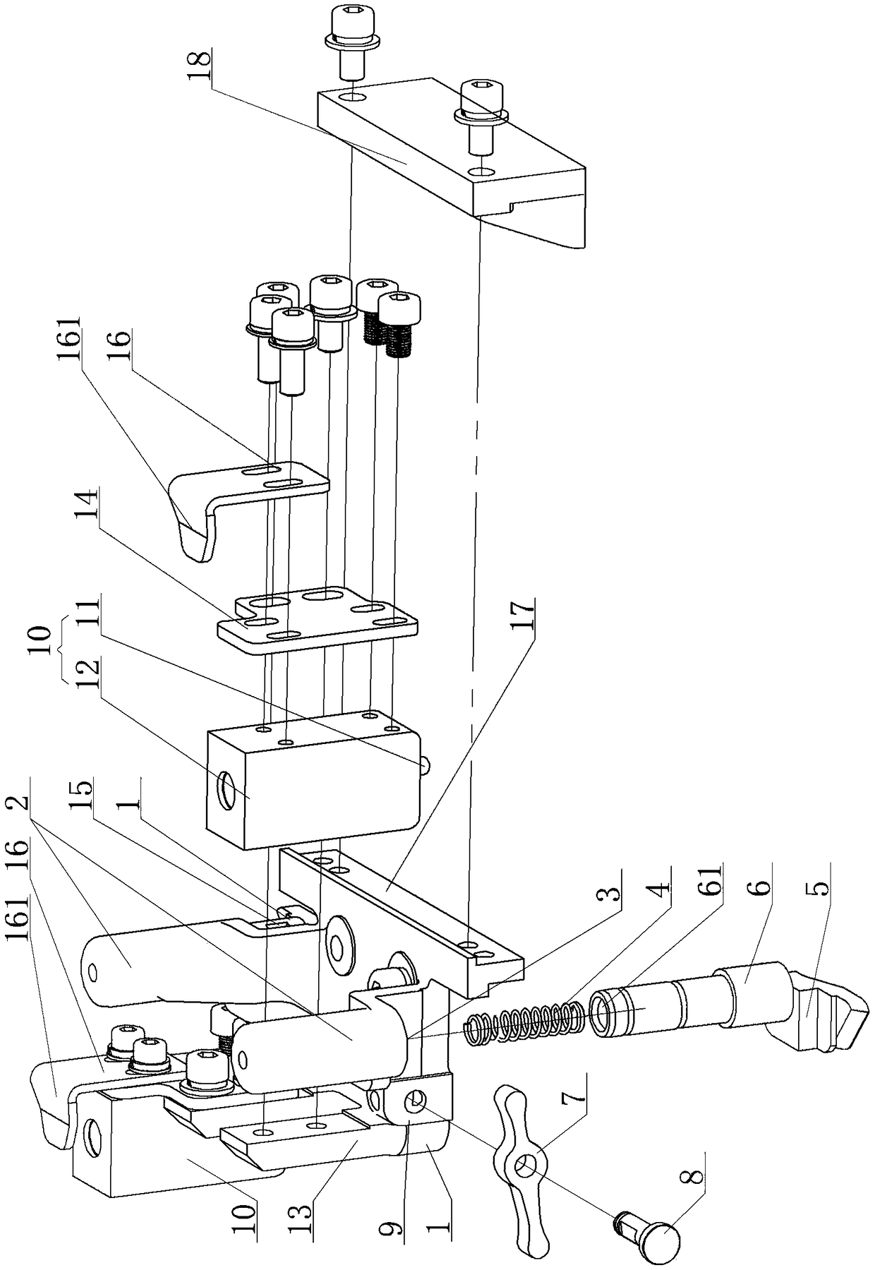
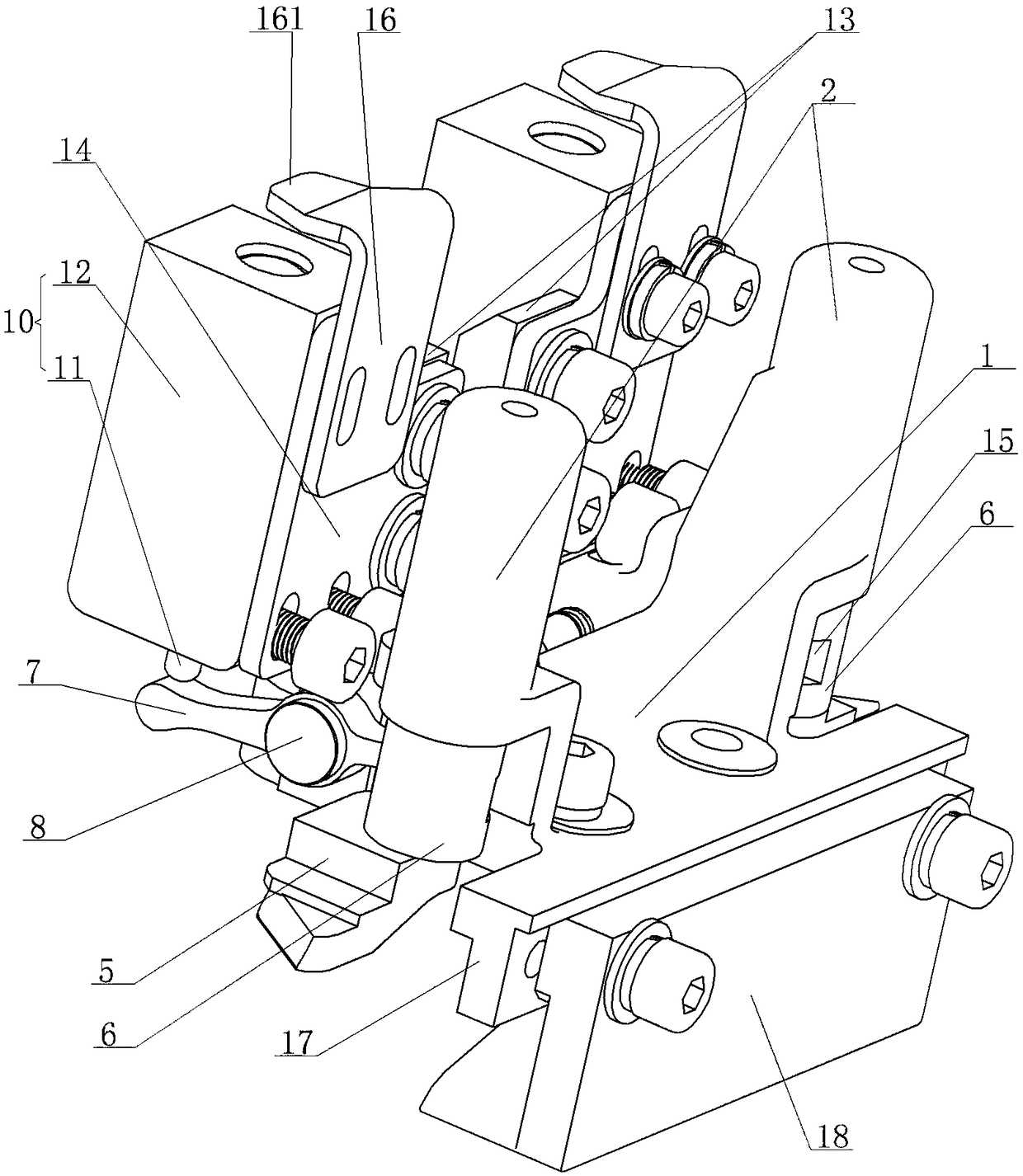
[0017] An electromagnet push pin mechanism, see figure 1 , figure 2 : It includes a mounting seat 1, and the two sides of the mounting seat 1 are respectively provided with a push pin cam seat 2, and each push pin cam seat 2 is provided with a vertical guide hole 3 from bottom to top, and the vertical guide hole 3 is arranged with The linear spring 4, the upper part of the corresponding push pin triangle 5 is inserted into the vertical guide hole 3 through the upper column end 6, and the lower end of the linear spring 4 is mounted on the top, and the position of the upper column end 6 exposed in the vertical guide hole 3 is connected with One end of the transmission connecting rod 7, the middle position in the length direction of the transmission connecting rod 7 is pivoted to the rotating shaft positioning protrusion 9 through the rotating shaft 8, and the lower end telescopic shaft 11 of the electromagnet 10 is arranged directly above the other end of the transmission conne...


PUM


Abstract

The invention provides a needle-pushing electromagnet mechanism, which quickly drives needle pushing triangles to ascend and descend, without a reset time for a driving device, thereby shortening thecorresponding knitting time, and improving the knitting efficiency. The needle-pushing electromagnet mechanism comprises a mounting seat, wherein the two sides of the mounting seat are respectively provided with the needle pushing triangles, and each of the needle pushing triangles is provided with a vertical guiding hole from bottom to top; a linear spring is arranged in the vertical guiding hole; the upper part of the corresponding needle pushing triangle is inserted into the vertical guide hole through an upper column end, and the lower end of the linear spring is mounted to the top thereof; at a position exposed to the vertical guide hole, the upper column end is connected to one end of a transmission connecting rod; a middle portion of the longitudinal direction of the transmission link is pivotally connected to a rotating shaft positioning boss by a rotating shaft, and a lower end telescopic shaft of the electromagnet is arranged just above the other end of the transmission connecting rod; and a shell of the electromagnet is fixed to an installation upper convex plate at a corresponding position.

Description

technical field [0001] The invention relates to the technical field of a push needle structure of a flat knitting machine, in particular to an electromagnet push needle mechanism. Background technique [0002] The existing push needle mechanism of the flat knitting machine, which holds the guide rail through the magnet, and then drives the drive of the push needle cam. In actual use, the position of the magnet needs to be reset. Long weaving time. Contents of the invention [0003] In view of the above problems, the present invention provides an electromagnet pusher mechanism, which quickly drives the lifter cam up and down, the driving device does not need to reserve a reset time, shortens the corresponding knitting time, and improves the knitting efficiency. [0004] An electromagnet push pin mechanism, characterized in that: it includes a mounting seat, the two sides of the mounting seat are respectively provided with push pin cam seats, and each of the push pin cam se...

Claims


Application Information

Patent Timeline
Patent Type & Authority Applications(China)
IPC IPC(8): D04B15/36
CPCD04B15/36
Inventor 金永良孙健高钧棠徐玉婷徐备松
Owner JIANGSU JINLONG TECHNOLOGY CO LTD
Why Eureka
Try Eureka