Scaffold for building

A kind of scaffolding and construction technology, applied in the direction of construction, building structure, house structure support, etc., can solve the problem that the device cannot be moved, and achieve the effect of protecting the device

Inactive Publication Date: 2018-11-13
浙江花园建设集团有限公司
View PDF7 Cites 9 Cited by
  • Summary
  • Abstract
  • Description
  • Claims
  • Application Information

AI Technical Summary

Problems solved by technology

[0002] For example, the patent number CN201710202018.3 is a kind of scaffolding for construction, which relates to the technical field of construction equipment; it includes a fixed frame, a scaffolding board, a vertical horizontal bar, a scissor brace, a sliding frame, a lifting mechanism, a sliding frame hanging point, and a fixed frame hanging point , sliding frame fixing part, fixed frame fixing part; the bottom of described fixed frame is provided with scaffold board, and fixed frame is supported by some vertical horizontal rods, and some vertical horizontal rods are fixedly connected with scissors brace; described fixed frame and sliding frame Sliding connection, the fixed frame is provided with a fixed frame hanging point, and the sliding frame is provided with a sliding frame hanging point; the lifting mechanism is connected with the sliding frame hanging point, and the sliding frame is connected with the fixed frame hanging point through a wire rope; the fixed The frame and the sliding frame are respectively connected to the wall through the sliding frame fixing part and the fixed frame fixing part; the disadvantage of this invention is that the device cannot be moved

Method used


Image

  • Scaffold for building
  • Scaffold for building
  • Scaffold for building

Examples


specific Embodiment approach 1

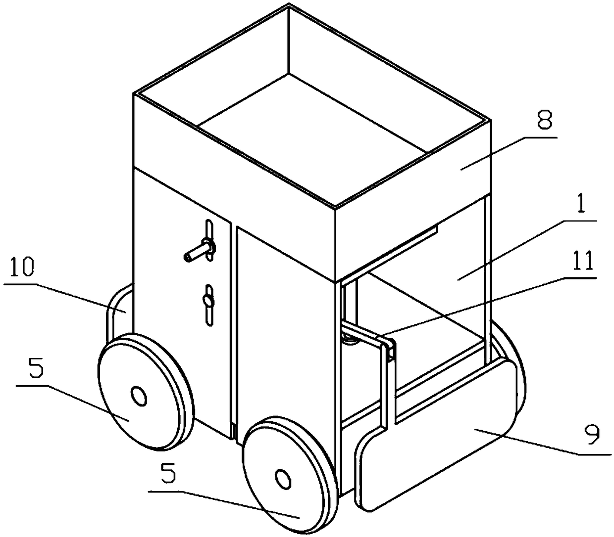
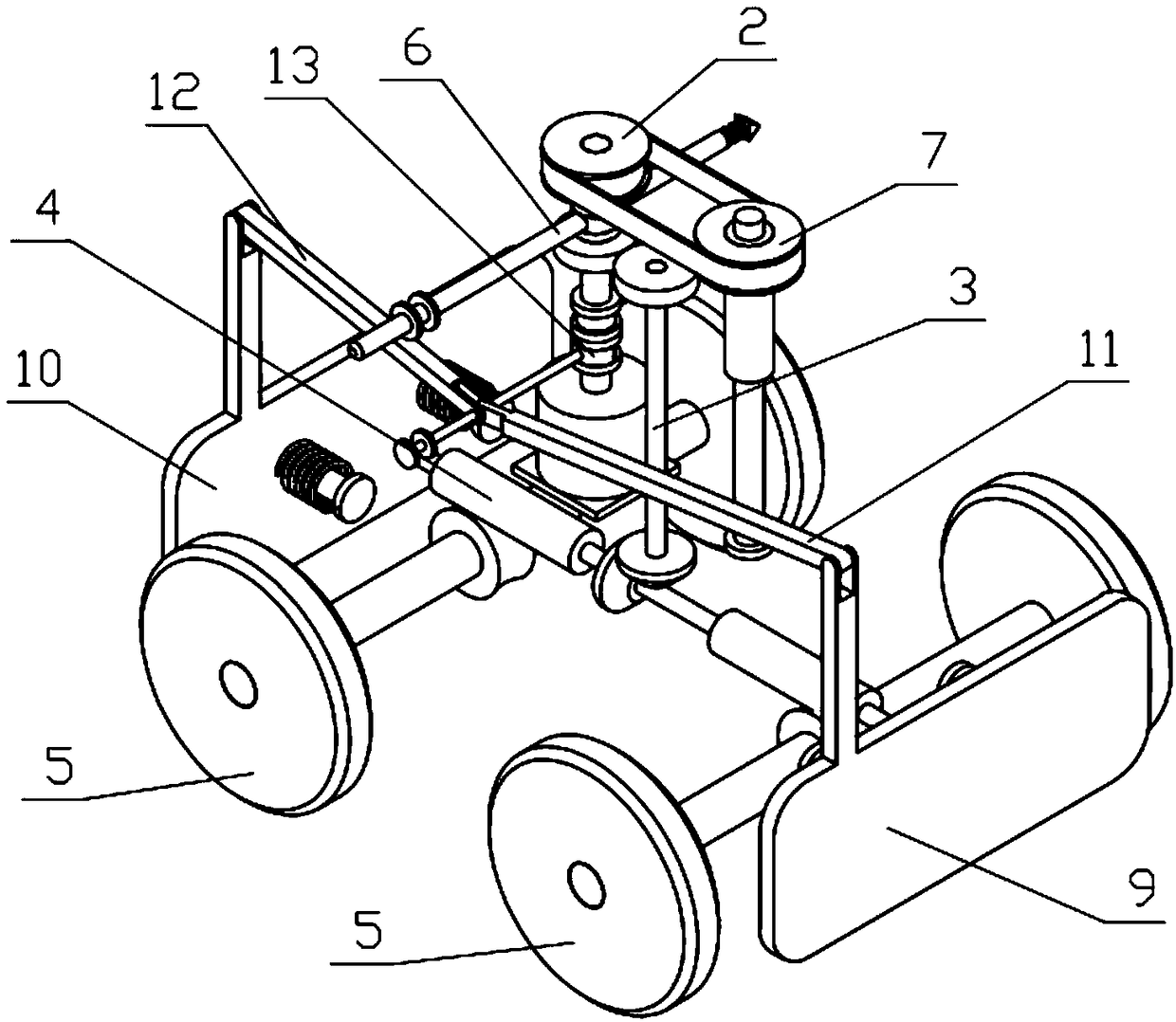
[0038] Combine below Figure 1-16 Describe this embodiment, a kind of scaffolding for construction, including integral bracket 1, power mechanism 2, transmission mechanism 3, worm mechanism 4, motion mechanism 5, control mechanism 6, lifting mechanism 7, lifting plate 8, touching front plate 9, After touching the rear plate 10, connecting rod I11, connecting rod II12 and shift fork 13, the power mechanism 2 is fixedly connected to the overall support 1, and two moving mechanisms 5 are symmetrically arranged front and back, a transmission mechanism 3, a worm mechanism 4 and two The two moving mechanisms 5 are all rotatably connected on the integral support 1, the power mechanism 2 and the transmission mechanism 3 are driven through gear engagement, the transmission mechanism 3 and the worm mechanism 4 are driven through gear engagement, and the worm mechanism 4 and the movement mechanism 5 are transmitted through the worm gear engagement. The left end of the control mechanism 6...

specific Embodiment approach 2

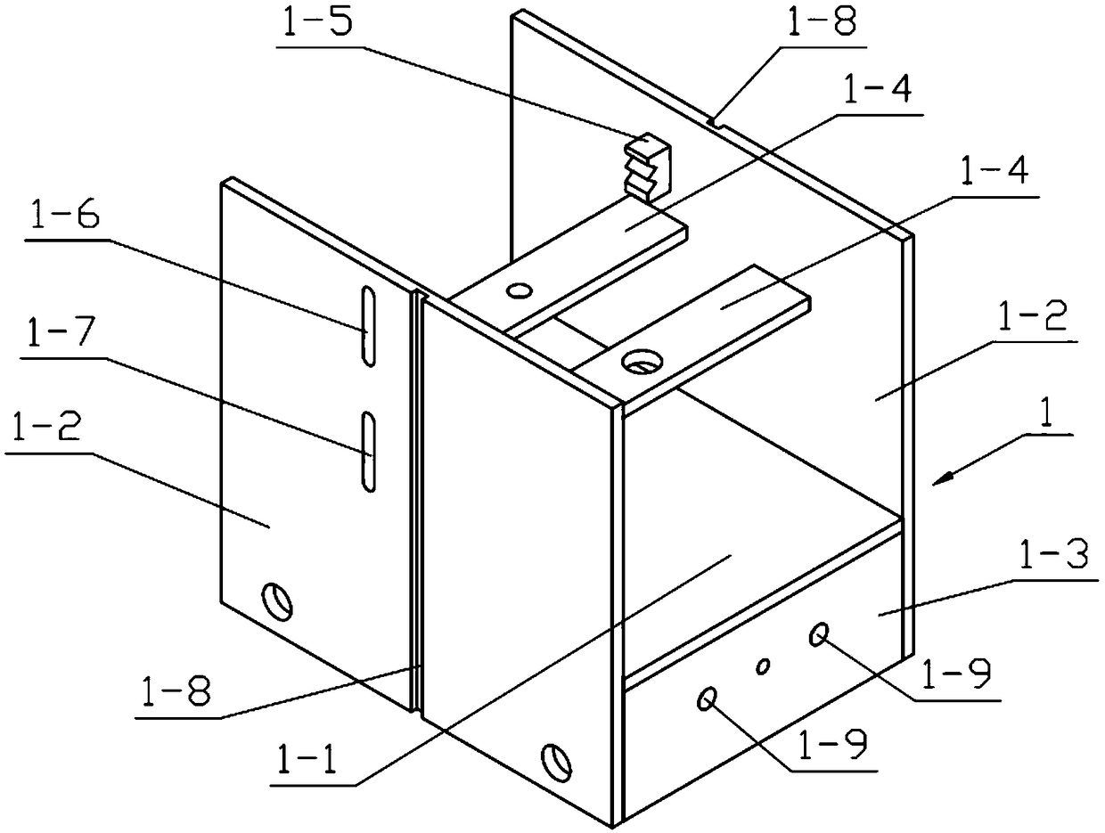
[0039] Combine below Figure 1-16 This embodiment will be described. This embodiment will further describe Embodiment 1. The integral bracket 1 includes a bottom plate 1-1, left and right side plates 1-2, front and rear side plates 1-3, support plates 1-4, and W-shaped clamping joints. Body 1-5, vertical sliding groove I1-6, vertical sliding groove II1-7, lifting sliding groove 1-8 and circular through hole 1-9, left and right side plates 1-2 are left and right symmetrically arranged with two, two Two left and right side plates 1-2 are respectively fixedly connected to the left and right ends of the base plate 1-1. 1, two support plates 1-4 are symmetrically arranged on the left and right sides, and the left and right ends of the two support plates 1-4 are respectively fixedly connected to the two left and right side plates 1-2, and the W-shaped snap-in body 1- 5 Welded on the left and right side plates 1-2 at the right end, the vertical sliding groove I1-6 and the vertical s...

specific Embodiment approach 3

[0040] Combine below Figure 1-16 Describe this embodiment, this embodiment will further explain the second embodiment, the power mechanism 2 includes a motor 2-1, a sliding side tooth I2-2, a connecting key I2-3, a power shaft 2-4, and a side tooth 2- 5. Power gear 2-6, sliding side teeth II 2-7, power pulley 2-8 and connecting key II 2-9, sliding side gear I 2-2 is slidingly connected to the output shaft of motor 2-1 through connecting key I 2-3 On, power shaft 2-4 rotates and is connected to the upper end side tooth 2-5 of motor 2-1 output shaft and is fixedly connected to the lower end of power shaft 2-4, and power gear 2-6 and power pulley 2-8 are all provided with Side teeth, the power gear 2-6 is connected to the middle end of the power shaft 2-4 in rotation, the power pulley 2-8 is connected to the upper end of the power shaft 2-4 in rotation, and the sliding side teeth II 2-7 slide through the connection key II 2-9 Connected to the power shaft 2-4, the sliding side g...


PUM


Abstract

The invention relates to a building device, in particular to a scaffold for building. The scaffold comprises a whole bracket, a power mechanism, a transmission mechanism, a worm mechanism, movement mechanisms, a control mechanism, a lifting mechanism, a lifting plate, a touch front plate, a touch rear plate, a connecting rod I, a connecting rod II and a shifting fork. The scaffold can move, ascendand descend through power switching on the power mechanism; when the control mechanism is clamped at the upper end of a W-shaped clamping body, a sliding side tooth II and a power belt wheel on the power mechanism are engaged, and the lifting mechanism moves; when the control mechanism is clamped at the lower end of the W-shaped clamping body, the sliding side tooth II and a power gear on the power mechanism are engaged, and the movement mechanisms move to move the scaffold; and when the scaffold encounters obstacles during moving, the touch front plate or the touch rear plate squeezes a compression spring I or a compression spring II to push the shifting fork to move, a sliding side tooth I and a side tooth on the power mechanism are disengaged, power on the power mechanism is switched off, and thus the effect of protecting the scaffold is achieved.

Description

technical field [0001] The invention relates to a construction device, in particular to a construction scaffold. Background technique [0002] For example, the patent number CN201710202018.3 is a kind of scaffolding for construction, which relates to the technical field of construction equipment; it includes a fixed frame, a scaffolding board, a vertical horizontal bar, a scissor brace, a sliding frame, a lifting mechanism, a sliding frame hanging point, and a fixed frame hanging point , sliding frame fixing part, fixed frame fixing part; the bottom of described fixed frame is provided with scaffold board, and fixed frame is supported by some vertical horizontal rods, and some vertical horizontal rods are fixedly connected with scissors brace; described fixed frame and sliding frame Sliding connection, the fixed frame is provided with a fixed frame hanging point, and the sliding frame is provided with a sliding frame hanging point; the lifting mechanism is connected with the...

Claims


Application Information

Patent Timeline
Patent Type & Authority Applications(China)
IPC IPC(8): E04G1/22E04G1/24
CPCE04G1/22E04G1/24E04G2001/244
Inventor 杜华东蒋国成金杭军金君强胡卿笑朱爱明
Owner 浙江花园建设集团有限公司
Why Eureka
Try Eureka