Damping device for mechanical equipment

A technology of vibration damping device and mechanical equipment, applied in mechanical equipment, spring/shock absorber, vibration suppression adjustment, etc., can solve the problems of inconvenient installation, difficult equipment support, affecting mechanical operation, etc., to achieve high consistency and reduce impact , the effect of uniform support

Inactive Publication Date: 2018-11-13
张阳康
View PDF7 Cites 5 Cited by
  • Summary
  • Abstract
  • Description
  • Claims
  • Application Information

AI Technical Summary

Problems solved by technology

Its shortcoming is that the existing shock absorbing device cannot solve the shock absorbing problem very well, thereby affecting our operation to the machine, and it is inconvenient to install, and it is also not conducive to use.
[0004] However, the above-mentioned solution has the following defects in use: due to the complex structure of the mechanical equipment, the characteristics of large weight and uneven weight distribution, when using the above-mentioned device, only direct shock-absorbing support can be performed on the installation place, and it is difficult to support the entire equipment. With stable support, the sinking distance of the heavy parts of the equipment is greater than that of the light parts, which is not conducive to maintaining the horizontal state of the equipment, and when the equipment vibrates, the force provided by each device is not consistent, which is not conducive to shock absorption

Method used


Image

  • Damping device for mechanical equipment
  • Damping device for mechanical equipment
  • Damping device for mechanical equipment

Examples


Embodiment Construction

[0022] The technical solutions in the embodiments of the present invention will be clearly and completely described below in conjunction with the embodiments of the present invention. Apparently, the described embodiments are only some of the embodiments of the present invention, not all of them. Based on the embodiments of the present invention, all other embodiments obtained by persons of ordinary skill in the art without making creative efforts belong to the protection scope of the present invention.

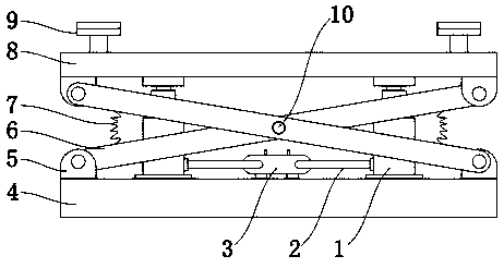
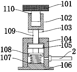
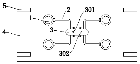
[0023] Such as Figure 1-4 As shown, a vibration damping device for mechanical equipment includes a vibration damping assembly 1, a bottom plate 4 and a top plate 8, the bottom plate 4 and the top plate 8 are welded and fixed with ear plates 5, and the ear plates 5 are rotatably connected with The support rod 6, the shock absorbing assembly 1 is installed between the bottom plate 4 and the top plate 8, the shock absorbing assembly 1 includes a cylinder 104, a piston 105 is mo...


PUM


Abstract

The invention discloses a damping device for mechanical equipment. The damping device comprises damping modules, a base plate and a top plate; lug plates are fixedly welded on the base plate and the top plate; support rods are rotationally connected between the lug plates; the damping modules comprise cylinders; pistons are movably arranged in the cylinders, and are fixed on ejector rods; adjusting sleeves are fixedly welded at the tops of the ejector rods; the adjusting sleeves are connected with fixed plates through studs; communicating pipes are arranged on the side walls of the cylinders;and the other ends of the communicating pipes communicate with pressure tanks. Through cross arrangement of the support rods, the top plate can be always kept horizontal, so that the equipment is always located in a horizontal state; the damping modules synchronously communicates with the pressure tanks through the communicating pipes, so that the vibration is effectively absorbed through the support force of each damping module; and the support heights of the damping modules can be adjusted through rotating of the studs, so that the height consistency of each damping module is guaranteed, andmeanwhile, the uniform support force is provided.

Description

technical field [0001] The invention belongs to the technical field of vibration damping devices for mechanical equipment, and in particular relates to a vibration damping device for mechanical equipment. Background technique [0002] The shock absorber is mainly used to suppress the shock when the spring rebounds after absorbing the shock and the impact from the road surface. When passing through uneven roads, although the shock-absorbing spring can filter the vibration of the road surface, the spring itself will reciprocate, and the shock absorber is used to suppress this spring jumping. Its shortcoming is that the existing shock absorbing device can not solve the shock absorbing problem well, thereby has influenced our operation to machinery, and installation is inconvenient, also is unfavorable for using. [0003] For this reason, the patent application number is CN201710392591.5, which discloses a mechanical equipment shock absorber, its structure includes a lower shoc...

Claims


Application Information

Patent Timeline
Patent Type & Authority Applications(China)
IPC IPC(8): F16F15/023F16F15/04
CPCF16F15/022F16F15/0232F16F15/04F16F2238/026
Inventor 张阳康
Owner 张阳康
Why Eureka
Try Eureka