

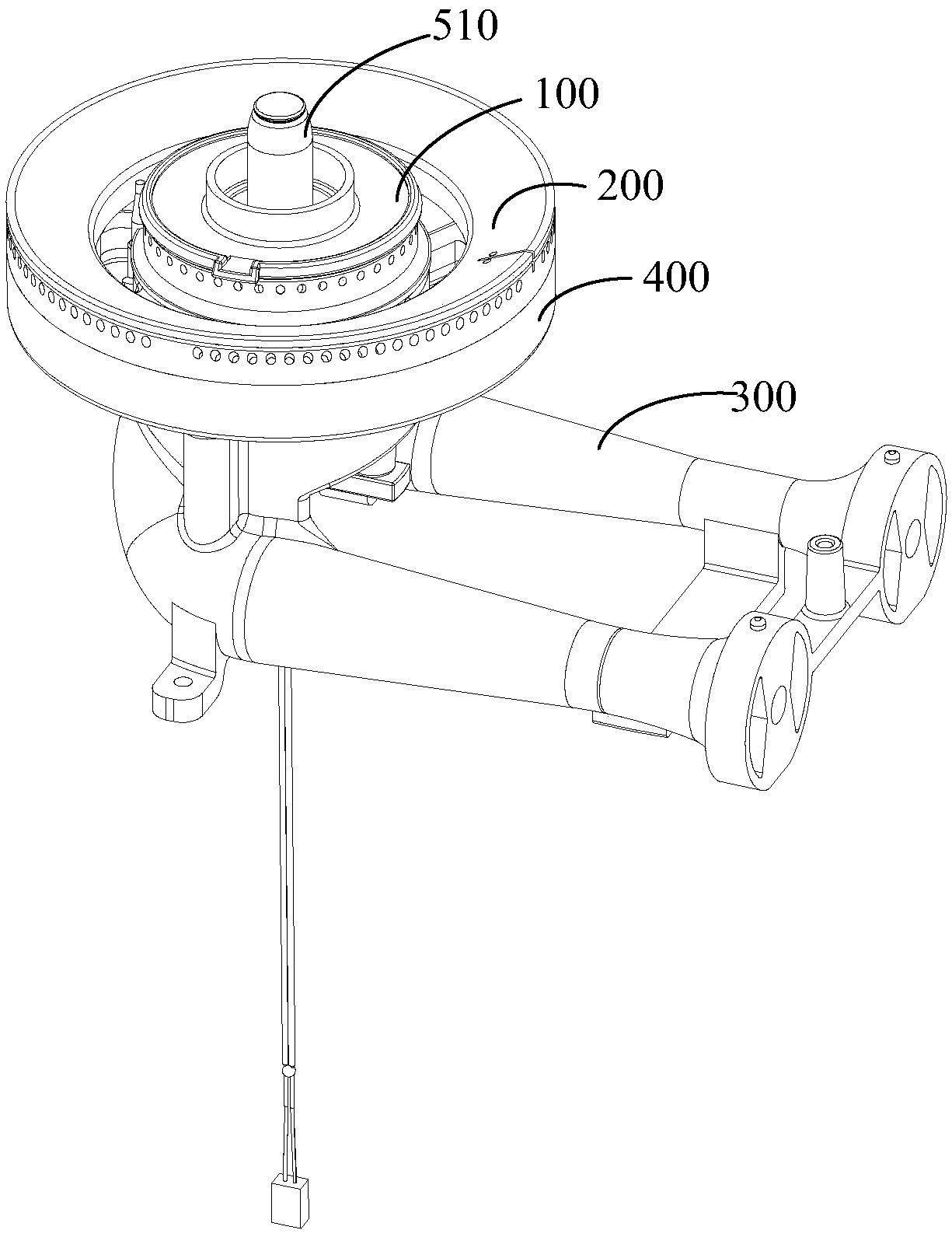
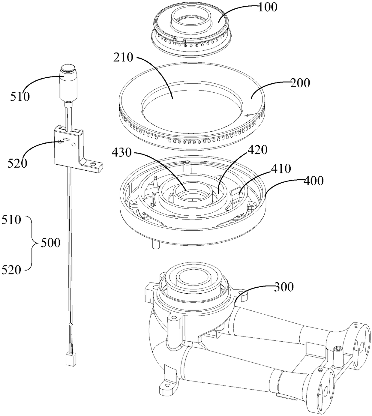
Furnace head assembly, combustor and gas stove
A burner and burner technology, which is applied to burners, gas fuel burners, combustion methods, etc., can solve the problems of increasing the overall height of the burner assembly, increasing the ejector tube and the burner, etc., so as to facilitate heat dissipation and reduce energy. , the effect of increasing the cooling space
- Summary
- Abstract
- Description
- Claims
- Application Information
AI Technical Summary
Problems solved by technology
Method used
Image

Examples
Embodiment Construction
[0055] The following will clearly and completely describe the technical solutions in the embodiments of the present invention with reference to the accompanying drawings in the embodiments of the present invention. Obviously, the described embodiments are only part of the embodiments of the present invention, not all of them. Based on the embodiments of the present invention, all other embodiments obtained by persons of ordinary skill in the art without creative efforts fall within the protection scope of the present invention.
[0056] It should be noted that all directional indications (such as up, down, left, right, front, back...) in the embodiments of the present invention are only used to explain the relationship between the components in a certain posture (as shown in the accompanying drawings). Relative positional relationship, movement conditions, etc., if the specific posture changes, the directional indication will also change accordingly.
[0057] In addition, the ...
PUM
 Abstract
Description
Claims
Application Information