Heat exchange system and water heater with the same

A heat exchange system and heat exchanger technology, applied in superheaters, fluid heaters, lighting and heating equipment, etc., can solve problems such as liquid return and overheating under high temperature conditions, so as to avoid liquid shock, improve practicability and reliability performance and improve user experience

Pending Publication Date: 2018-11-13
格力电器(杭州)有限公司 +1
0 Cites 4 Cited by

AI-Extracted Technical Summary

Problems solved by technology

[0003] The main purpose of the present invention is to provide a heat exchange system and a water heater with it, so as to solve the p...

Method used

In the present embodiment, adopt capillary and valve body structure to arrange side by side, can prevent the situation that this heat exchange system returns liquid when heating at low temperature, have avoided the situation that compressor produces liquid hammer effectively, effectively The practicability and reliability of the heat exchange system are improved, and the user experience is improved. As shown in Figure 1, the capillary tube 41 and the valve body structure 42 are respectively arranged on two branches, so that the refrigerant in the pipeline between the second heat exchang...

Abstract

The invention provides a heat exchange system and a water heater with the same. The heat exchange system comprises an exhaust opening of a compressor, wherein the exhaust opening communicates with a first inlet end of a first heat exchanger, a first outlet end of the first heat exchanger communicates with a first inlet end of a second heat exchanger, the first outlet end of the first heat exchanger communicates with an inlet end of a third heat exchanger, an outlet end of the third heat exchanger communicates with a first inlet end of a gas-liquid separator, and a first outlet end of the gas-liquid separator communicates with an intake opening of the compressor; and a caterpillar pipe and a valve structure are arranged on a pipeline for connecting the second heat exchanger and the third heat exchanger, and the caterpillar pipe and the valve structure are arranged in parallel. By arranging the caterpillar pipe and the valve structure side by side, the low-temperature back-flowing and high-temperature overheating problems of the heat exchange system can be prevented, the liquid impact condition of the compressor is effectively avoided, the practicability and reliability of the heat exchange system are effectively improved, and the use experience of the user is improved.

Application Domain

Technology Topic

EngineeringVapor–liquid separator +3

Image

  • Heat exchange system and water heater with the same

Examples

  • Experimental program(1)

Example Embodiment

[0019] It should be noted that the embodiments in this application and the features in the embodiments can be combined with each other if there is no conflict. Hereinafter, the present invention will be described in detail with reference to the drawings and in conjunction with the embodiments.
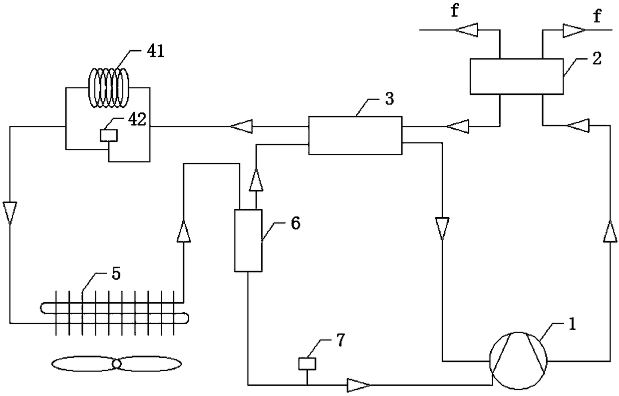
[0020] It should be noted that the terms used here are only for describing specific implementations, and are not intended to limit the exemplary implementations according to the present application. As used herein, unless the context clearly indicates otherwise, the singular form is also intended to include the plural form. In addition, it should also be understood that when the terms "comprising" and/or "including" are used in this specification, they indicate There are features, steps, operations, devices, components, and/or combinations thereof.
[0021] It should be noted that the terms "first" and "second" in the specification, claims, and drawings of this application are used to distinguish similar objects, and are not necessarily used to describe a specific sequence or sequence. It should be understood that the terms used in this way can be interchanged under appropriate circumstances so that the embodiments of the present application described herein can be implemented in an order other than those illustrated or described herein, for example. In addition, the terms "including" and "having" and any variations of them are intended to cover non-exclusive inclusions. For example, a process, method, system, product, or device that includes a series of steps or units is not necessarily limited to the clearly listed Those steps or units may include other steps or units that are not clearly listed or are inherent to these processes, methods, products, or equipment.
[0022] For ease of description, spatially relative terms can be used here, such as "above", "above", "above the surface", "above", etc., to describe as shown in the figure Shows the spatial positional relationship between one device or feature and other devices or features. It should be understood that the spatially relative terms are intended to encompass different orientations in use or operation other than the orientation of the device described in the figure. For example, if the device in the drawing is inverted, then a device described as "above other devices or structures" or "above other devices or structures" will be positioned as "below other devices or structures" or "on Under other devices or structures". Thus, the exemplary term "above" can include both orientations "above" and "below". The device can also be positioned in other different ways (rotated by 90 degrees or in other orientations), and the relative description of the space used here is explained accordingly.
[0023] Now, exemplary embodiments according to the present application will be described in more detail with reference to the accompanying drawings. However, these exemplary embodiments can be implemented in a variety of different forms, and should not be construed as being limited to the embodiments set forth herein. It should be understood that these embodiments are provided to make the disclosure of this application thorough and complete, and to fully convey the concept of these exemplary embodiments to those of ordinary skill in the art. In the drawings, for clarity, it may be enlarged. The thicknesses of layers and regions are described, and the same reference numerals are used to denote the same devices, and thus their description will be omitted.
[0024] Such as figure 1 As shown, according to an embodiment of the present invention, a heat exchange system is provided.
[0025] Specifically, the heat exchange system includes a compressor 1, a first heat exchanger 2, a second heat exchanger 3, a third heat exchanger 5, and a gas-liquid separator 6 connected to each other. The exhaust port of the compressor 1 communicates with the first inlet end of the first heat exchanger 2, the first outlet end of the first heat exchanger 2 communicates with the first inlet end of the second heat exchanger 3, and the first The first outlet end of the heat exchanger 2 communicates with the inlet end of the third heat exchanger 5, the outlet end of the third heat exchanger 5 communicates with the first inlet end of the gas-liquid separator 6, and the gas-liquid separator 6 The first outlet end of is communicated with the suction port of the compressor 1. Wherein, the pipeline connecting the second heat exchanger 3 and the third heat exchanger 5 is provided with a capillary tube 41 and a valve body structure 42, and the capillary tube 41 and the valve body structure 42 are arranged in parallel.
[0026] In this embodiment, the capillary tube and the valve body structure are arranged side by side, which can prevent the heat exchange system from liquid back during low-temperature heating, effectively avoid the compressor’s liquid hammer, and effectively improve the The practicality and reliability of the heat exchange system improve the user experience. Such as figure 1 As shown, the capillary tube 41 and the valve body structure 42 are respectively arranged on two branches, and this arrangement can effectively achieve throttling of the refrigerant in the pipeline between the second heat exchanger 3 and the third heat exchanger 5.
[0027] Preferably, in order to further improve the reliability of the valve body structure 42, the valve body structure 42 is configured as an electronic expansion valve.
[0028] In order to improve the performance of the heat exchange system, the heat exchange system also includes an air supply pipeline. The first end of the supplemental gas pipeline is connected to the second outlet end of the gas-liquid separator 6, and the second end of the supplementary gas pipeline is connected with the supplementary gas port of the compressor 1. Part of the supplementary gas pipeline is connected from the second heat exchanger 3. The second inlet end of the second heat exchanger 3 enters the second heat exchanger 3 and passes through the second outlet of the second heat exchanger 3.
[0029] Further, the first heat exchanger 2 is an air cooler. Such as figure 1 As shown in f, the air cooler has multiple hot water outlet ports, which are connected to the user unit.
[0030] Preferably, the second heat exchanger 3 is a regenerator. The third heat exchanger 5 is an evaporator. A solenoid valve 7 is provided on the pipeline connecting the first outlet end of the gas-liquid separator 6 and the suction port of the compressor 1.
[0031] In this embodiment, the compressor 1 may be a single-stage compressor or a multi-stage compressor. Among them, the refrigerant passed into the compressor 1 is carbon dioxide.
[0032] The heat exchange system in the above embodiment can also be used in the technical field of heat exchanger equipment, that is, according to another aspect of the present invention, a water heater is provided, including a heat exchange system, and the heat exchange system is the heat exchange in the above embodiment system.
[0033] Specifically, the electronic expansion valve is a high-pressure electronic expansion valve. By using a capillary tube and a high-pressure electronic expansion valve in parallel to form a double throttling device, the throttling device is given the function of self-regulation, which solves the problem of liquid return under low temperature conditions and high temperature conditions. The problem of overheating conditions and the limitations of operating conditions has increased the CO 2 The range of use of the heat pump.
[0034] Such as figure 1 As shown, the first heat exchanger 2 has CO for heat exchange 2 The first inlet and second outlet, the water inlet for heat exchange, the water outlet for heat exchange, the second heat exchanger 3 has high-pressure CO for heat exchange 2 The first inlet port, high pressure CO for heat exchange 2 The second outlet port, low pressure CO for heat exchange 2 The second inlet port, low pressure CO for heat exchange 2 The second exit end. High pressure electronic expansion valve with CO 2 Entry and exit. The third heat exchanger 5 has an outlet end and an inlet end for heat exchange, and an air inlet and an air outlet. The gas-liquid separator 6 has a 2 The first inlet end and the second outlet end, and the second outlet end for oil passage, can withstand high pressure of 12MPa. The gas-liquid separator is connected in series between the regenerator and the evaporator through the low-pressure pipeline to separate the gas phase and the liquid phase that have not evaporated completely. The oil outlet of the gas-liquid separator is connected with the oil return port of the compressor through a pipeline, and the oil return solenoid valve in series in the middle is used to control the opening and closing of the oil return passage. The double throttling device includes a capillary tube and an electronic expansion valve. The capillary tube and the electronic expansion valve are connected in parallel to the high-pressure CO of the regenerator 2 Outlet and evaporator CO 2 A double throttling device is formed between the inlets. The electronic expansion valve is connected in parallel on the basis of the original capillary throttling device, and the opening degree of the electronic expansion valve can be automatically adjusted according to different working conditions.
[0035] In addition to the above, it should be noted that "one embodiment", "another embodiment", "embodiment", etc. referred to in this specification refer to specific features, structures, or features described in conjunction with the embodiment. The features are included in at least one embodiment described generally in this application. The appearance of the same expression in multiple places in the specification does not necessarily refer to the same embodiment. Furthermore, when describing a specific feature, structure, or characteristic in combination with any embodiment, it is claimed that combining other embodiments to implement such feature, structure, or characteristic also falls within the scope of the present invention.
[0036] In the above-mentioned embodiments, the description of each embodiment has its own focus. For parts that are not described in detail in an embodiment, reference may be made to related descriptions of other embodiments.
[0037] The above are only preferred embodiments of the present invention and are not used to limit the present invention. For those skilled in the art, the present invention can have various modifications and changes. Any modification, equivalent replacement, improvement, etc., made within the spirit and principle of the present invention shall be included in the protection scope of the present invention.

PUM

no PUM

Description & Claims & Application Information

We can also present the details of the Description, Claims and Application information to help users get a comprehensive understanding of the technical details of the patent, such as background art, summary of invention, brief description of drawings, description of embodiments, and other original content. On the other hand, users can also determine the specific scope of protection of the technology through the list of claims; as well as understand the changes in the life cycle of the technology with the presentation of the patent timeline. Login to view more.

Similar technology patents

Energy-saving device with high-pressure liquid storage and supply function and low-pressure gas-liquid separation function

PendingCN107763909APrevent liquid supply from gasPrevent liquid shockRefrigeration componentsEvaporatorEngineering
Owner:江苏世林博尔制冷设备有限公司

Liquid impact preventing liquid storage tank

InactiveCN110873485AImprove liquid removal efficiencyPrevent liquid shockRefrigeration componentsSpoilerEngineering
Owner:惠州道尚智能科技有限公司

Environment test device based on suction superheat degree and air volume partition and control method thereof

InactiveCN111457630AReasonable operating conditionsPrevent liquid shockCompression machines with non-reversible cycleTemperature measurement of flowing materialsPhysicsAir volume
Owner:JIANGSU TUOMILUO ENVIRONMENTAL TEST EQUIP CO LTD

Stepped direct action solenoid valve

InactiveCN107143684ASmall load impactPrevent liquid shockOperating means/releasing devices for valvesPressure relieving devices on sealing facesValve openingValve seat
Owner:浙江盈亿机械股份有限公司

Classification and recommendation of technical efficacy words

  • Improve availability and reliability
  • Prevent liquid shock

Multipurpose pump system

ActiveCN105180515AImprove efficiencyPrevent liquid shockHeat pumpsPower unitHeating power
Owner:屹立顺通(山东)节能环保科技有限公司

Medical refrigeration container hot gas defrosting system for temperature and humidity control

InactiveCN104634019APrevent liquid shockAvoid affecting the heat transfer effectMechanical apparatusCorrosion preventionRefrigeration plantEvaporator
Owner:QINGDAO AUCMA ULTRA LOW TEMPERATURE FREEZING MACHINES
Why Eureka
Try Eureka