Gas-liquid separator

A technology of gas-liquid separator and gas outlet pipe, which is applied in the direction of refrigeration and liquefaction, refrigeration components, refrigerators, etc., and can solve the problems that the wear and liquid hammer phenomenon of the compressor cannot be effectively improved, and the oil return performance of the compressor cannot be effectively improved. Achieve stable oil return, ensure lubricity, and reduce wear

Active Publication Date: 2015-09-30
GUANGDONG EUROKLIMAT AIR CONDITIONING & REFRIGERATION
View PDF8 Cites 7 Cited by
  • Summary
  • Abstract
  • Description
  • Claims
  • Application Information

AI Technical Summary

Problems solved by technology

Of course, the gas outlet pipe in the existing gas-liquid separator is also provided with a plurality of oil outlet holes with a certain height difference at intervals, such as the gas-liquid separator disclosed in Patent No. 201020260544.9. There are three oil outlet holes, and the oil return range of the gas-liquid separator can be increased by adding two oil outlet holes, but these oil return holes cannot effectively improve the wear and liquid hammer phenomenon of the compressor, and must be changed by changing the oil return hole. The hole diameter improves the oil return performance of the compressor; another example discloses a new type of gas-liquid separator in the application number 201120334666.2. For example, when the liquid level of the gas-liquid separator changes frequently, these oil return holes can return oil. For example, when oil stratification occurs, these oil return holes can also return oil normally. The above papers record that in the case of changing the cooling capacity of the system, the settings of these oil return holes cannot effectively improve the oil return performance of the compressor, and it is necessary to return to the fundamental problem of changing the diameter of the oil return hole.

Method used


Image

  • Gas-liquid separator
  • Gas-liquid separator
  • Gas-liquid separator

Examples


Embodiment Construction

[0036] The present invention is further described in conjunction with the following examples.

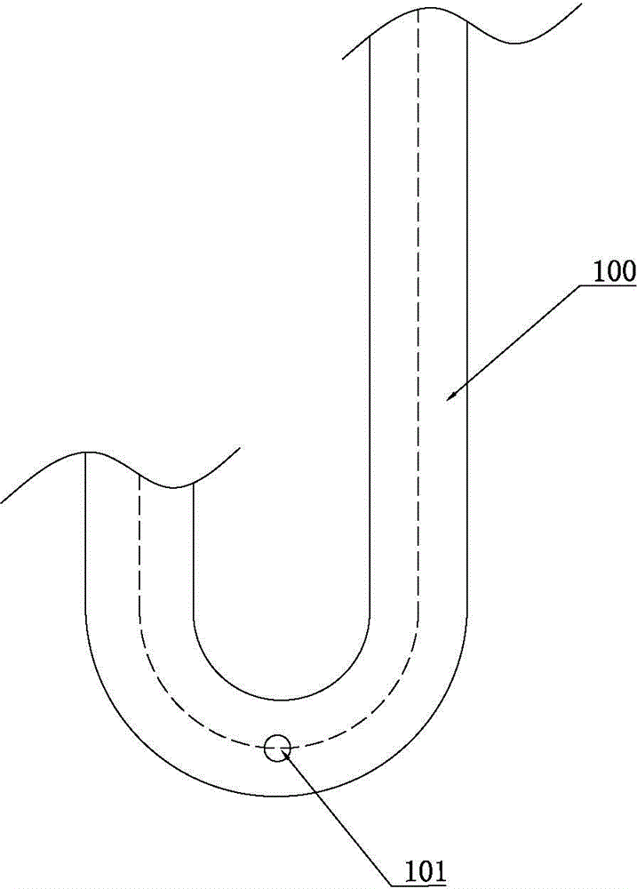
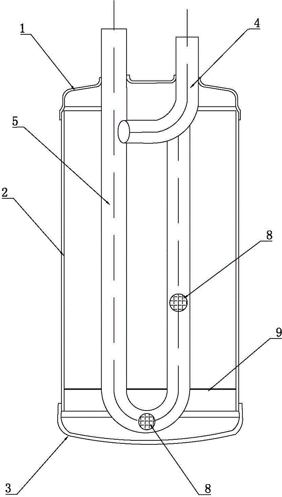
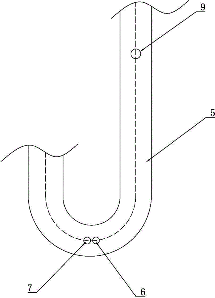
[0037] A specific embodiment of a gas-liquid separator of the present invention, such as figure 2 with image 3 As shown, its structure includes a closed cylinder body, an air inlet pipe 4 and a U-shaped air outlet pipe 5, wherein the cylinder body is composed of an upper end cover 1, a middle cylinder body 2 and a lower end cover 3, and the upper end cover 1 and the lower end cover 3 are respectively welded with At both ends of the middle cylinder body 2, the air intake pipe 4 is welded to the upper end cover 1, the air intake end of the air intake pipe 4 is above the upper end cover 1, the air outlet end of the air intake pipe 4 passes through the upper end cover 1 and inserted into the cylinder body, and the U-shaped air outlet pipe 5 is built into the cylinder and fixed by the fixing plate 10, and the fixing plate 10 is fixed on the inner wall of the middle cylinder body 2, th...


PUM


Abstract

The invention provides a gas-liquid separator, and belongs to the technical field of air conditioner. The structure of the gas-liquid separator comprises a closed drum body, an air inlet pipe and a U-shaped air outlet pipe. The air inlet end of the air inlet pipe is arranged outside the drum body. The air outlet end of the air inlet pipe is inserted into the drum body. The U-shaped air outlet pipe is arranged on the drum body, and the air outlet end of the U-shaped air outlet pipe is stretched out of the drum body. Two oil return holes which are adjacent and are arranged side by side are formed in one side face of the U-shaped bottom of the U-shaped air outlet pipe. Oil returning is conducted simultaneously, the stable oil return can be achieved, the oil return quantity can be controlled, and backflow quantity of liquid refrigerant is reduced under the regulation of refrigerant oil attenuating, so that the lubricity of the refrigerant oil is guaranteed, the oil return quantity inside the compressor is guaranteed, therefore wear to the running components in the compressor can be reduced, and liquid slugging of the compressor can be prevented effectively at the same time. According to the gas-liquid separator, the principle that the oil return property of the compressor is improved by changing the hole diameter of an oil return hole in the prior art, and an oil return property of the compressor is improved by arranging the two adjacent and abreast oil return holes.

Description

technical field [0001] The invention relates to the technical field of air conditioning, in particular to a gas-liquid separator applied in an air conditioning system. Background technique [0002] The ambient temperature range of the air conditioning system is relatively large. If the vapor capacity of the evaporator is insufficient under low temperature conditions, or the control mechanism of the air conditioning system does not respond in time, it may cause a large amount of liquid refrigerant to return to the suction side of the compressor. In order to prevent a large amount of liquid refrigerant from entering the compressor, a gas-liquid separator is generally installed on the suction side of the compressor. The main function of the gas-liquid separator is to separate the gas and liquid in the refrigerant to prevent the compressor from sucking liquid during operation. Too much refrigerant will cause wear of the moving parts of the compressor, and even cause liquid shock...

Claims


Application Information

Patent Timeline
Patent Type & Authority Applications(China)
IPC IPC(8): F25B43/00
CPCF25B43/00
Inventor 吴永训李世刚陈千驹余张波
Owner GUANGDONG EUROKLIMAT AIR CONDITIONING & REFRIGERATION
Why Eureka
Try Eureka