Fuel injector for dual fuel common rail system

一种燃料喷射器、喷射器的技术,应用在燃料喷射装置、特殊燃料喷射装置、装料系统等方向,能够解决泄漏、燃料交叉泄漏等问题

Inactive Publication Date: 2014-05-07
CATERPILLAR INC
View PDF4 Cites 13 Cited by
  • Summary
  • Abstract
  • Description
  • Claims
  • Application Information

AI Technical Summary

Problems solved by technology

However, the structure of the injectors results in cross leaks between fuels, fuel leaks into the engine cylinders, and cumulative tolerances that can lead to large performance differences when the fuel injectors are mass-produced

Method used


Image

  • Fuel injector for dual fuel common rail system
  • Fuel injector for dual fuel common rail system
  • Fuel injector for dual fuel common rail system

Examples


Embodiment Construction

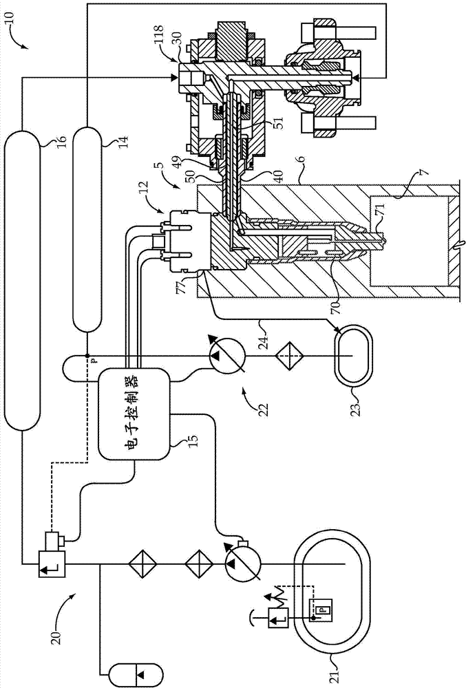
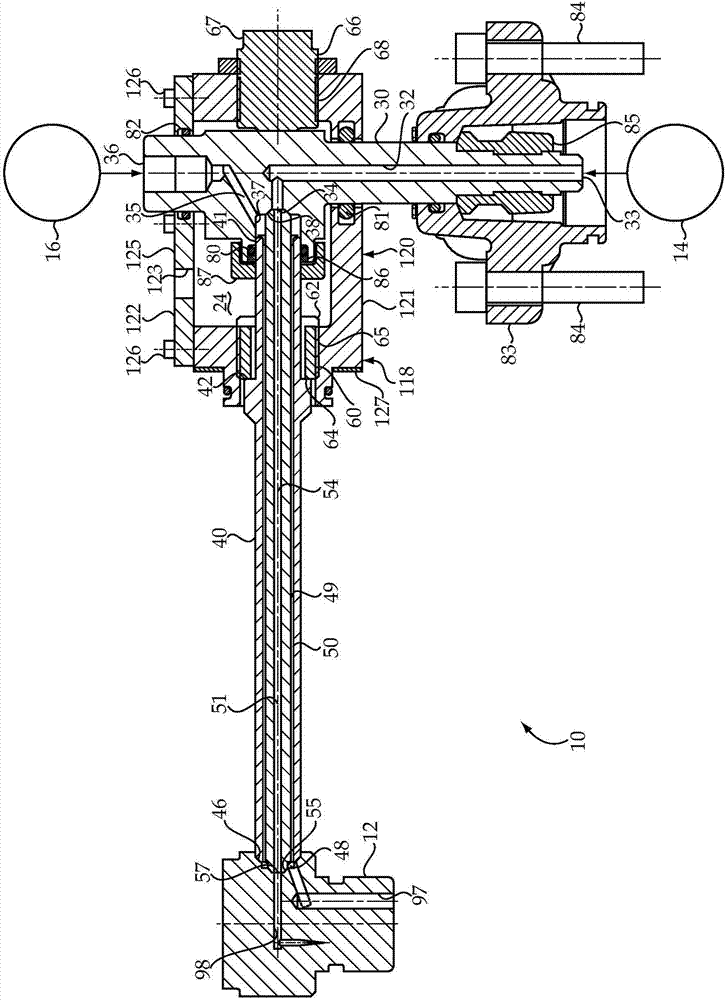
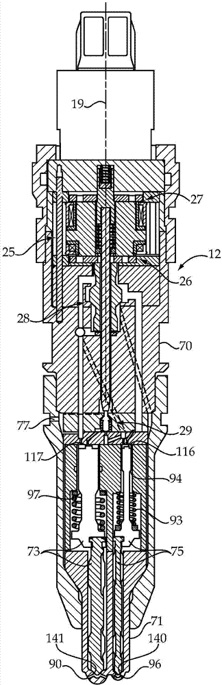
[0014] see figure 1 , the engine 5 according to the present invention uses a dual fuel common rail system 10 . The engine 5 comprises an engine housing 6 defining a plurality of cylinders 7, only one of which is shown in the figure. Dual fuel system 10 includes a plurality of fuel injectors 12 (only one shown) each including an injector body 70 having features configured to inject gaseous and / or liquid fuel directly Spray into the top part 71 in one of the cylinders 7 of the engine. The dual fuel system 10 includes a plurality of concentric outer tubes 40 and inner tubes 50 each extending into the engine housing 6 between a quill 30 and one of the fuel injectors 12 . Each inner tube 50 is compressed between a conical seat on the associated tube shaft 30 and a conical seat on one of the fuel injectors 12 . Thus, each engine cylinder 7 has an associated fuel injector 12 , an outer tube 40 , an inner tube 50 and a tube shaft 30 . Dual fuel system 10 includes a gaseous fuel co...


PUM


Abstract

A duel fuel system (10) includes a plurality of fuel injectors (12) that have a non-injection configuration, a liquid fuel injection configuration, a gaseous fuel injection configuration and a combined fuel injection configuration. Each of the fuel injectors (12) is fluidly connected to a gaseous fuel common rail (14) and a liquid fuel common rail (16). Each of the fuel injectors (12) includes a three way gas control valve (28) and a three way liquid control valve (29) that move along a common centerline (19). A gas control chamber (92) of each fuel injector (12) is fluidly connected to the liquid fuel common rail (16) by two passages (152, 154) in parallel when the gas control valve member (105) is in a first position corresponding to the non-injection configuration. The liquid control chamber (95) of each fuel injector (12) is also fluidly connected to the liquid fuel common rail (16) by two passages (150, 151) in parallel when the liquid control valve (29) is in a first position, again corresponding to the non-injection configuration.

Description

technical field [0001] The present invention relates generally to dual fuel common rail systems, and more particularly to dual fuel injectors for separately supplying gaseous fuel and liquid fuel to an engine. Background technique [0002] Gas fueled engines are known to be capable of clean combustion relative to compression ignition engines. However, gaseous fuels are notoriously difficult to successfully ignite (ignite). Some gaseous fueled engines utilize spark plugs, while other engines are known to utilize small amounts of distilled diesel fuel that are compression ignited to ignite larger quantities of gaseous fuel. Practical space constraints in and around the engine often make it difficult to find room for all the plumbing and hardware associated with feeding the two different fuels to each combustion chamber. US Patent 7,373,931 teaches a dual fuel engine utilizing a small amount of and compression ignited distillate diesel fuel to ignite a larger amount of gaseou...

Claims


Application Information

Patent Timeline
Patent Type & Authority Applications(China)
IPC IPC(8): F02M43/04F02D19/06F02D19/08F02M55/02F02M61/18
CPCF02D19/0694F02D19/10F02M43/04F02M47/027F02M55/02F02M63/0019F02M63/0035F02M63/0064F02M63/008F02M2200/44Y02T10/30F02D19/0647
Inventor 金会山
Owner CATERPILLAR INC
Why Eureka
Try Eureka