
Electrical connector and electrical connector device

An electrical connector and connector technology, applied in the direction of two-part connecting device, parts of the connecting device, protective grounding/shielding device of the connecting part, etc., can solve the problem of damage to the locking mechanism, parts without supporting locking pieces, electrical connection Damage and other problems, to achieve a firm maintenance effect

Active Publication Date: 2018-11-13
I PEX CO LTD
View PDF7 Cites 0 Cited by
  • Summary
  • Abstract
  • Description
  • Claims
  • Application Information

AI Technical Summary

Problems solved by technology

[0003] However, in the locking mechanism provided in the conventional electrical connector device, there is no member for supporting the locking piece against an external force applied in the direction of pulling out the mated electrical connector (matched connector).
Therefore, it cannot be said that the limit load that can resist the external force in the pulling direction is sufficient, and it can be considered that even when a relatively weak external force is applied, the engagement relationship of the locking mechanism may be released or the locking mechanism may be generated. damage, resulting in damage to the electrical connection

Method used


Image

  • Electrical connector and electrical connector device
  • Electrical connector and electrical connector device
  • Electrical connector and electrical connector device

Examples


Embodiment Construction

[0094] Hereinafter, an embodiment in which the present invention is applied to a coaxial-type electrical connector using a thin-wire coaxial cable as a signal transmission medium will be described in detail based on the drawings.

[0095] [About the overall structure of the coaxial electrical connector device]

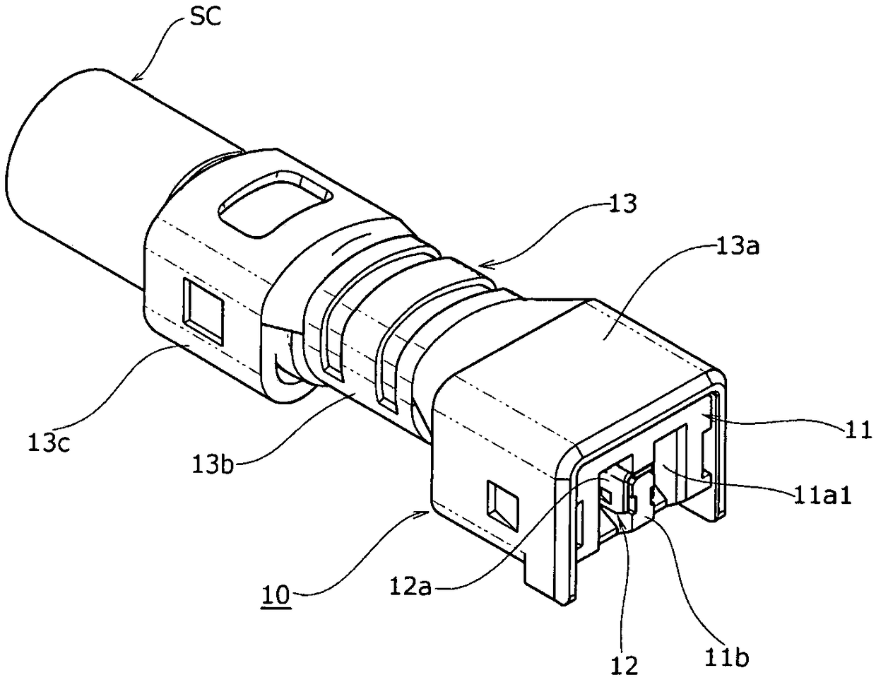
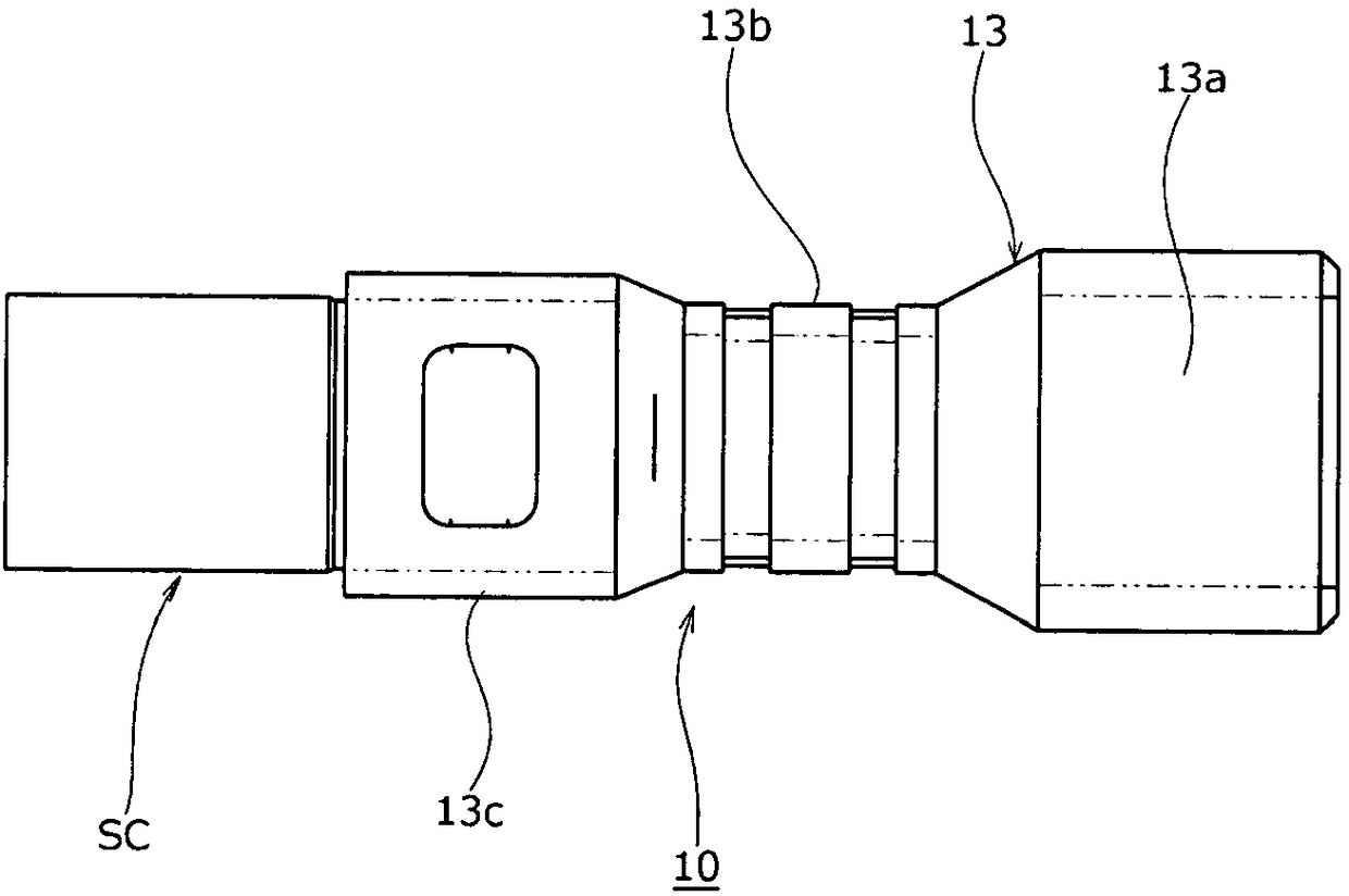
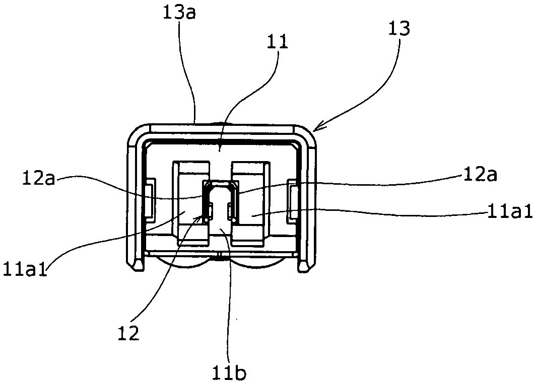
[0096] First, as Figure 1 to Figure 5 The plug connector 10 of the object connector (first connector) shown is configured to be connected with a terminal portion of a thin-line coaxial cable SC as a cable-like signal transmission medium, as Figure 13 ~ Figure 17 The illustrated receptacle connector 20 of the coaxial electrical connector (second connector) according to one embodiment of the present invention is configured to be mounted on a wiring board (not shown). In addition, the plug connector 10 is inserted and fitted into the receptacle connector 20 along the extending direction of the mounting surface (principal surface) of the wiring board, and is detached in...


PUM


Abstract

The invention provides an electrical connector and an electrical connector device to allow a fit-in state between electrical connectors to be firmly maintained. Elastic arm-shaped members (23d) disposed on a conductive shell member (23) so as to elastically displace to a direction orthogonal to a fit-in direction of a mating connector (10) are each provided with an engaging piece (23e) having a connector contact surface (23el) which the mating connector (10) faces from the depth in the fit-in direction and a shell contact surface (23e2) which a part of the conductive shell member (23) faces from the front in the fit-in direction. When an external force is applied to the mating connector (10) in a fit-in state to a removing direction opposite to the fit-in direction, the engaging piece (23e) is brought into a state of being interposed between the mating connector (10) and the conductive shell member (23). This avoids a situation in which the engaging piece (23e) is removed from the mating connector (10) to cause a lock release.

Description

technical field [0001] The present invention relates to an electrical connector and an electrical connector device configured to be fitted with a counterpart connector. Background technique [0002] In general, in various electrical equipment, an electrical connector device that electrically connects a pair of electrical connectors by fitting each other is widely used. In such an electrical connector device, when a pair of electrical connectors are fitted to each other, a lock mechanism is often employed in order to maintain the fitted state of the electrical connectors. For example, the so-called mechanical locking mechanism disclosed in the following patent document 1 etc. is a locking mechanism that obtains a fitting and holding force by using a mechanically engaged locking piece, and has a structure that pulls out in a direction opposite to the fitting direction. When an external force is applied to the mated electrical connector (matched connector) in the removal direc...

Claims


Application Information

Patent Timeline
Patent Type & Authority Applications(China)
IPC IPC(8): H01R24/00H01R13/631
CPCH01R13/631H01R24/00H01R2103/00H01R13/6273H01R13/6581H01R24/50H01R24/40H01R13/639H01R2101/00H01R9/05H01R13/40H01R13/648H01R9/053H01R9/0518H01R24/38H01R13/6271H01R4/2495H01R13/658H01R9/0509H01R13/6582H01R43/048H01R13/6592H01R13/6275
Inventor 山内贵生
Owner I PEX CO LTD
Learn More