Gas stove

A gas furnace and gas burner technology, applied in the direction of burner, combustion method, combustion type, etc., can solve the problem that the main body of the burner is difficult to disassemble, and achieve the effect of maintaining the relative state

Inactive Publication Date: 2012-07-04
RINNAI CORP
View PDF6 Cites 0 Cited by
  • Summary
  • Abstract
  • Description
  • Claims
  • Application Information

AI Technical Summary

Problems solved by technology

[0007] However, when a concave portion is provided on a panel or the like, the boiled soup will adhere to the concave portion of the panel or the protrusion of the burner body during cooking, making it difficult for the burner body to be removed from the burner body after the soup has solidified. panel removed

Method used


Image

  • Gas stove
  • Gas stove
  • Gas stove

Examples


Embodiment Construction

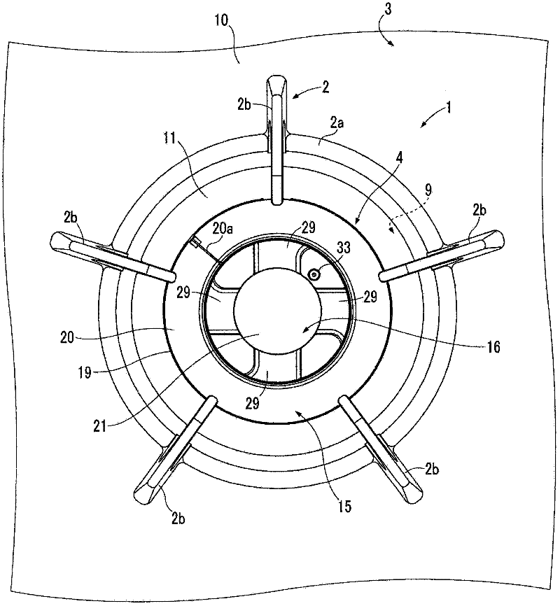
[0025] Hereinafter, embodiments of the present invention will be described with reference to the drawings. The gas stove of this embodiment is such as figure 1 and figure 2 The gas burner 1 and the fire support 2 provided around the gas burner 1 are provided as the main part is shown.

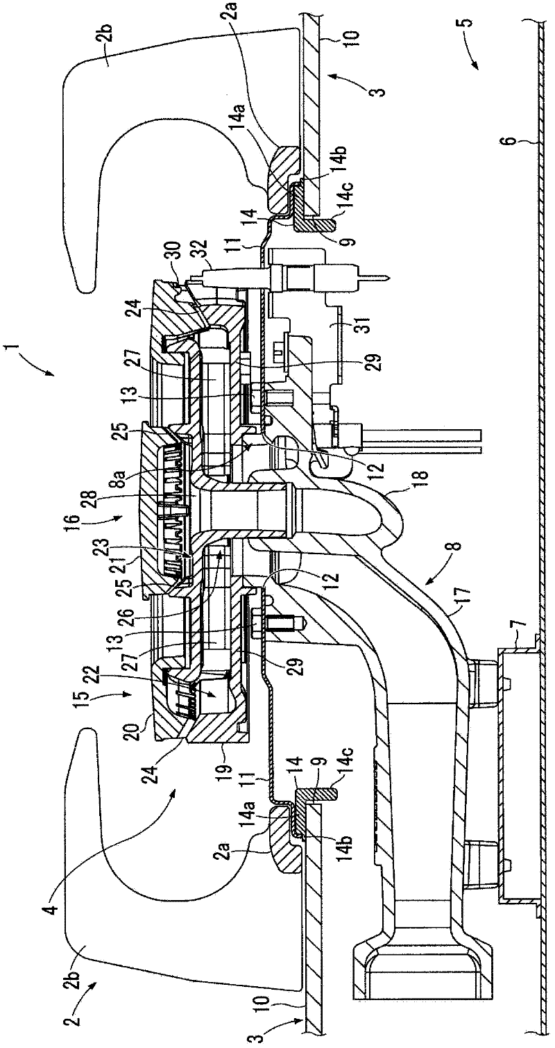
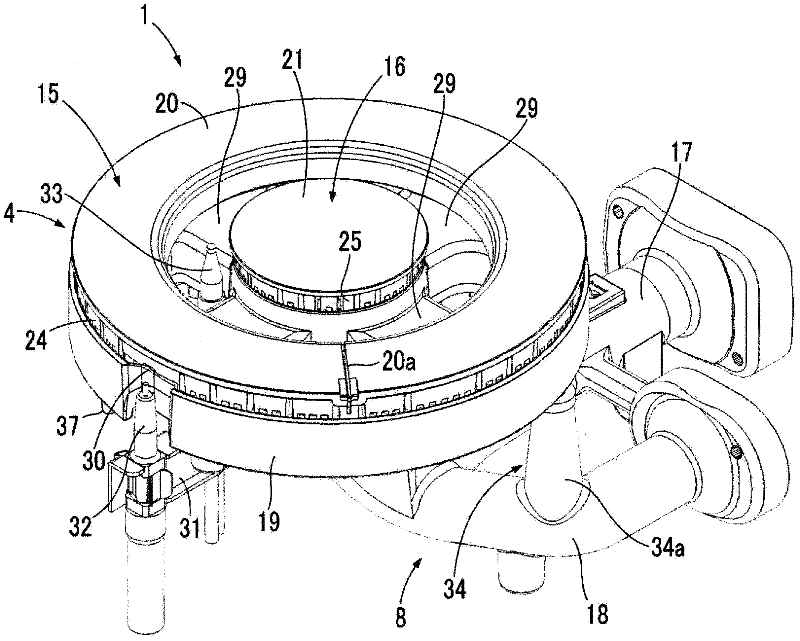
[0026] The gas burner 1 includes a burner body 4 and a mixing tube 8 . The burner main body 4 is exposed on the upper surface of the panel 3 constituting a part of the structure of the gas stove. The mixing tube 8 is accommodated inside the stove main body 5 constituting the structure of other parts of the gas stove, and is coupled and fixed to the bottom plate 6 of the stove main body 5 via the base portion 7 . The downstream end 8a of the mixing tube 8 opens upward.

[0027] Such as figure 2 As shown, the panel 3 is arranged to cover the top of the stove main body 5 . The panel 3 is composed of a panel body 10 formed with a burner installation opening 9 whose inner diameter is larger...


PUM


Abstract

The present invention provides a gas stove. A position on a lower surface of a combustor body (4), which is separated from a mixed gas inflow part (26) in a diameter direction, is provided with a concave chamber part (36) with an open lower end. A mixing tube (8) is provided with an anti-rotation component (34). The anti-rotation component (34) passes through a through hole (35) formed on a panel (8) and is jointed with the concave chamber part (36) of the combustor body (4), thereby preventing rotation of the combustor body (4). The gas stove can prevent hindering of overflowed soup to detachment of the combustor body relative to the mixing tube, and can reliably prevent rotation of the combustor body relative to the mixing tube.

Description

technical field [0001] The present invention relates to a gas stove provided with a gas burner. Background technique [0002] As a gas stove in the prior art, the following gas stove is known (for example, refer to Patent Document 1: Japanese Patent Laying-Open No. 3-164611 ( Figure five , Figure 6)). This gas stove is equipped with a gas burner, and a cylindrical mixing tube inflow portion is fitted to the downstream end of the mixing tube facing the burner installation opening of the panel, and the mixing tube inflow portion protrudes from the lower surface of the burner body. In the center of the burner, the mixed gas is supplied from the mixing tube to the burner body. [0003] In this gas burner, the spark plug and the burner base constructed as a part of the burner body are connected to and supported by the supporting member provided on the mixing tube, and the burner head constructed as the other part of the burner body is placed on the burner above the substrate. ...

Claims


Application Information

Patent Timeline
Patent Type & Authority Applications(China)
IPC IPC(8): F23D14/46F24C15/10
Inventor 荒松政男竹本安伸
Owner RINNAI CORP
Why Eureka
Try Eureka