
Connector and connector assembly

A connector component and a connector technology, which are applied in the direction of connections, components of connection devices, electrical components, etc., can solve problems such as large-scale buckle connectors, difficulty in increasing the size of buckle parts and buckle claws 881, etc. Achieve the effect of simple structure and increase the buckle strength

Active Publication Date: 2019-05-24
MOLEX INC
View PDF12 Cites 0 Cited by
  • Summary
  • Abstract
  • Description
  • Claims
  • Application Information

AI Technical Summary

Problems solved by technology

[0012] In order to prevent this, the dimensions (plate thickness, width, etc.) of the holding member and the holding claw 881 must be increased to increase the strength of the holding member and the holding claw 881, however, in recent years, electrical equipment, electronic equipment, etc. In an environment of continuous miniaturization, it becomes difficult to increase the size of the latching part and the latching claw 881 because it leads to an increase in the size of the latching connector.

Method used


Image

  • Connector and connector assembly
  • Connector and connector assembly
  • Connector and connector assembly

Examples


Embodiment Construction

[0113] Embodiments will be described in detail below with reference to the drawings.

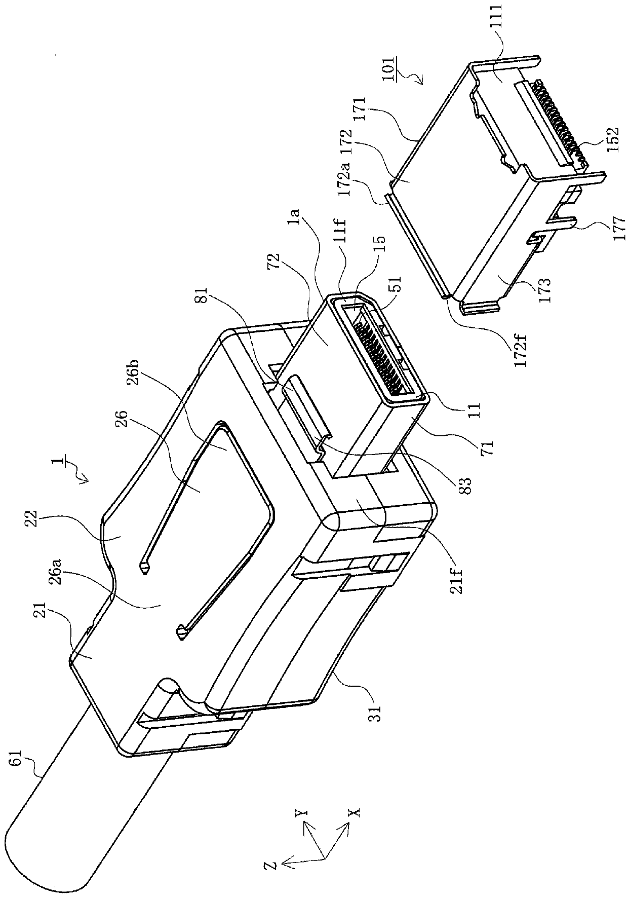
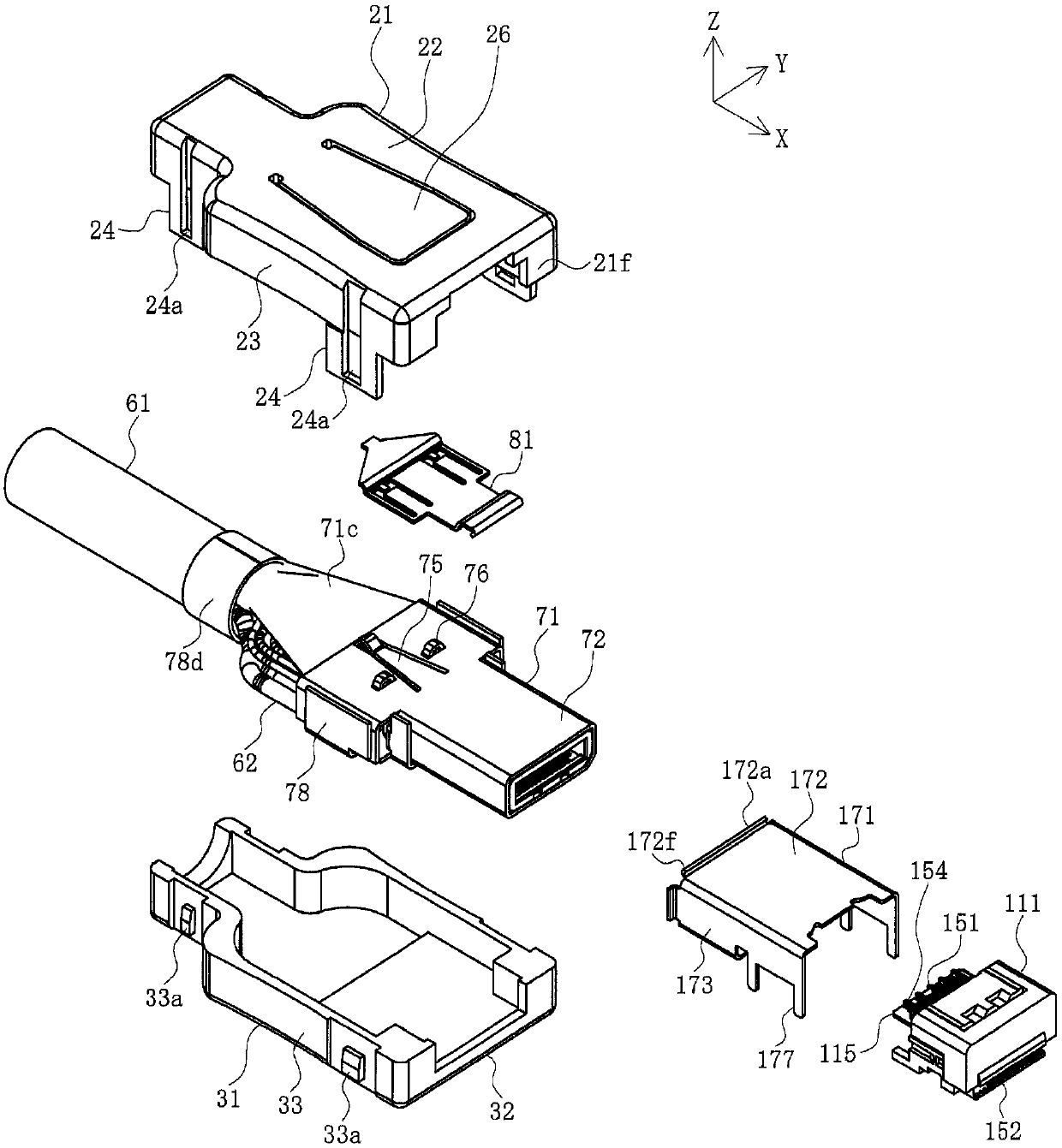
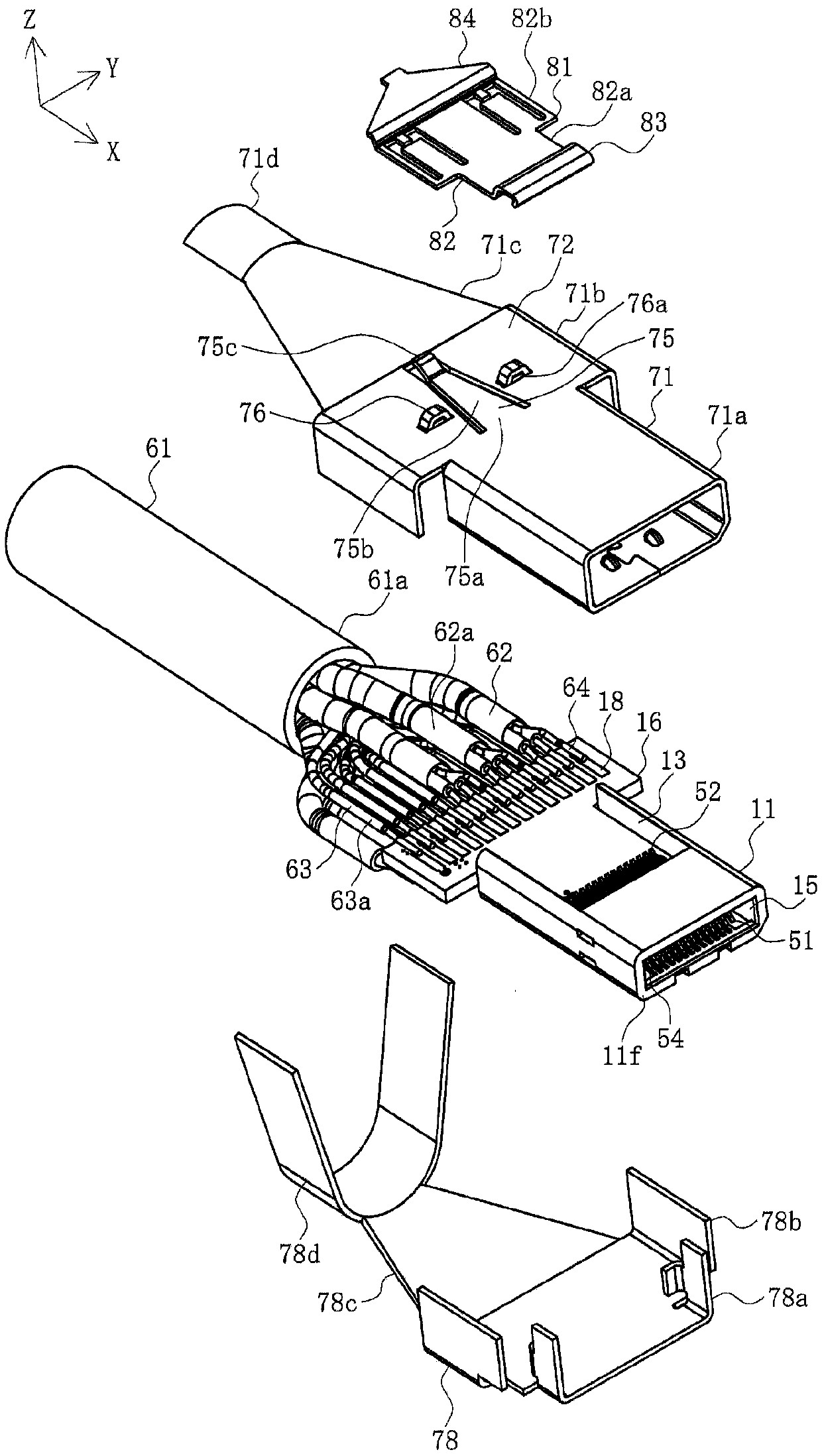
[0114] figure 1 is a perspective view showing a state before the wire connector and the board connector according to the embodiment are fitted. figure 2 is an exploded view of the wire connector and the board connector according to the present embodiment. image 3 is an exploded view of the wire connector according to the present embodiment except for the cover shell portion. Figure 4 is a perspective view seen from above of a part of the wire connector according to the present embodiment. Figure 5 is a perspective view seen from below of the portion of the wire connector according to the present embodiment. Figure 6A , Figure 6B is a perspective view of the buckling part of the wire connector according to this embodiment. Figure 7 It is a perspective view seen from below of the upper side cover case portion of the wire connector according to the present embodiment. Figure 8 is...


PUM


Abstract

The present invention can increase the fastening strength by a simple structure without increasing the size, so that even when an unexpected external force is applied, it is possible to secure the holding of the butt connector without releasing the fitting. A connector is proposed that includes a cover, a terminal (51) mounted in the housing, and a latching member (81). The top plate portion (72)of the cover includes a cantilever-shaped elastic piece portion formed by cutting a part of the top plate portion (72). The holding member (81) includes a body portion, a joint portion (83) connectedto the front end of the body portion, and an operation portion connected to the rear end of the body portion and capable of coming into contact with the free end portion of the elastic piece portion,and the holding member is swingably attached to the top plate portion (7nh2).

Description

technical field [0001] The invention relates to a connector and a connector assembly. Background technique [0002] Conventionally, small and low-profile connectors have been widely used to connect wires such as cables to substrates such as printed circuit substrates contained in electric equipment, electronic equipment, and the like. One problem associated with such connectors is that they are prone to disengagement or disconnection from the mating connector. Thus, a buckle connector including a buckle mechanism has been proposed (for example, see Patent Document 1). [0003] Figure 17 is a view showing a conventional snap connector. [0004] In the figure, 811 is a fitting portion of the base of the buckle connector connected to the end of the cable 861 . The fitting portion is a portion fitted with a butt connector (not shown). The base including the fitting portion 811 is made of an insulating resin material. The fitting portion 811 has a rectangular opening, and a...

Claims


Application Information

Patent Timeline
Patent Type & Authority Applications(China)
IPC IPC(8): H01R13/502H01R13/627H01R13/629
CPCH01R12/724H01R13/6275H01R13/6583H01R13/6272
Inventor 永濑里枝本桥信政山中学
Owner MOLEX INC
Learn More