A Copper Rotor Vacuum Die Casting Mold

A vacuum die-casting and copper rotor technology, applied in the field of vacuum die-casting, can solve the problems of increased and difficult mold sealing design, increase the exhaust capacity and vacuuming capacity, improve the exhausting capacity and vacuuming effect, and solve the problem of vacuuming Effect of Insufficient Exhaust Capacity

Active Publication Date: 2020-04-28
云南铜业科技发展股份有限公司
View PDF10 Cites 0 Cited by
  • Summary
  • Abstract
  • Description
  • Claims
  • Application Information

AI Technical Summary

Problems solved by technology

However, because the copper rotor die-casting technology needs to put the iron core stacked with silicon steel sheets into the mold before die-casting, the iron core and the mold form the cavity together, and the design of the core-pulling slider is required in the design of the die-casting mold to facilitate the iron core. Putting in and taking out the cast copper rotor after die-casting, the slider design is likely to become the most likely place for air leakage in the vacuum design, which not only adds difficulties to the mold sealing design of the copper rotor vacuum die-casting, but also is affected by high temperature after the silicon steel sheet is placed in the die-casting mold Continuous gas production puts forward higher requirements on the vacuum degree of the cavity and the capacity of vacuuming equipment
In addition, due to the high melting point of copper (the melting point of copper is 1083.4°C), the pouring temperature of cast copper is not lower than 1100°C, which makes the casting copper rotor vacuum die-casting technology face many technical difficulties

Method used


Image

  • A Copper Rotor Vacuum Die Casting Mold
  • A Copper Rotor Vacuum Die Casting Mold

Examples


Embodiment Construction

[0029] The mold structure of the present invention will be described in detail below in conjunction with the accompanying drawings.

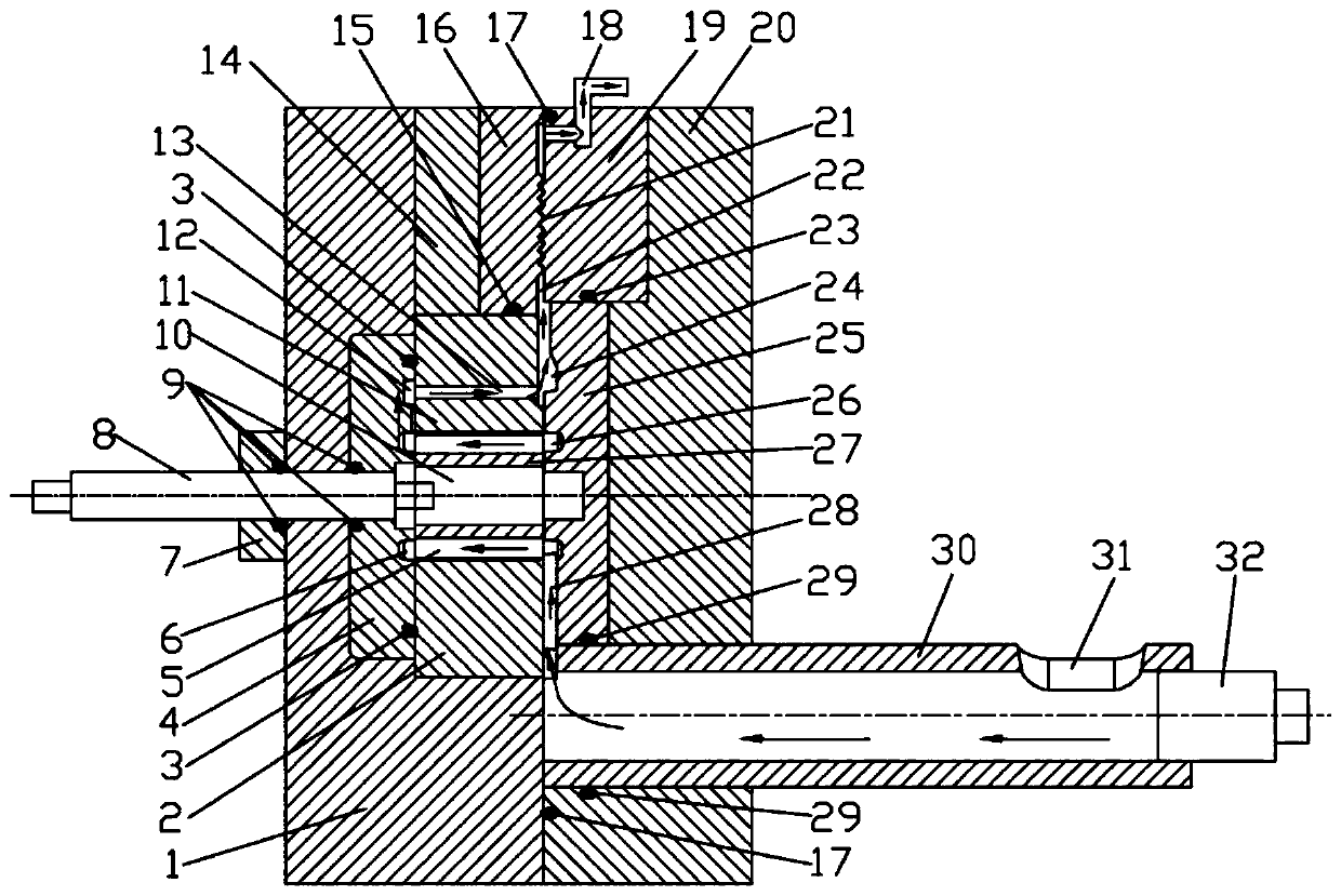
[0030] Such as figure 1The copper rotor vacuum die-casting mold shown includes a movable template 1, a static template 21 designed corresponding to the movable template 1, a core-pulling slider 14 installed on the movable template 1, and a movable mold insert set on the movable template 1 4 and the lower half block 2, the upper half block 11 installed on the core pulling slider 14, the static mold insert 25 and the pressure chamber 30 installed on the static template 20; the upper half block 11 and the lower half block 2 is provided with a dummy shaft 10, and an iron core 27 is stacked on the dummy shaft 10. One end of the iron core 27 is close to the movable mold insert 4, and the other end is set in the static mold after the movable template 1 and the static template 20 are closed. The static mold insert 25 on the template 20 fits closely; th...


PUM


Abstract

The invention relates to a copper rotor vacuum die-casting die which mainly comprises a movable formwork, a static formwork corresponding to the movable formwork, a core pulling sliding block mountedon the movable formwork, a moving die insert, a lower half block, an upper half block mounted on the core pulling sliding block, a static die insert and a pressing chamber, wherein the moving die insert and the lower half block are disposed on the movable formwork; and the static die insert and the pressing chamber are mounted on the static formwork. Exhaust blocks are arranged at the upper ends of the movable formwork and the static formwork respectively, each exhaust block is designed into three independent exhaust wave plates, and gaps of the exhaust wave plates on the two sides are smallerthan a gap of the middle exhaust wave plate. According to the copper rotor vacuum die-casting die, by the design of two exhaust channels, a mode of pumping out gas in the pressure casting process step by step is achieved, the exhaust area and the vacuumizing capability are improved, the exhaust capability is improved, the gas flow-out stroke is shortened, so that the gas is effectively pumped out, and the vacuum pressure of a cavity of the die-casting die is maintained at 10 KPa. The die is suitable for vacuum die casting of pure copper and copper alloy.

Description

technical field [0001] The invention belongs to the technical field of vacuum die-casting, and relates to a vacuum die-casting mold for an induction motor copper rotor, which is suitable for vacuum die-casting of pure copper and copper alloys. Background technique [0002] Copper's excellent electrical conductivity, excellent thermal conductivity, and high-pressure casting have the advantages of short molding cycle, high production efficiency, and environmental friendliness, making cast copper rotors widely used in high-efficiency motors with the implementation of motor energy efficiency policies, especially It has been applied in batches in the field of industrial motors such as reducers and in the field of low-speed motor vehicles. However, due to the existence of air in the cavity and pressure chamber in the die-casting process of ordinary die-casting technology, when the punch pushes the molten metal to fill the cavity, the air is drawn into the molten metal due to the t...

Claims


Application Information

Patent Timeline
Patent Type & Authority Patents(China)
IPC IPC(8): B22D17/14B22D17/22
CPCB22D17/145B22D17/2227
Inventor 梁栋杨红梅步毅杨旭杨华忠王光斌付志华邓陈兴浦周猛陈杰李继云冯俊峰刘大强晏得才吴文斌蔺高锋沈良弼宋昆杨鏐燚李辉卯明辉赵紧李健李金玉沈浩秦文红乐浩泽李永亮李玉龙郭泽兵李元棚吴荣兴赵宇航张明江李泽玲陆月明者正文杨学磊普春平永建东李嘉霖符光龙张堃管自涛李英访王必仕
Owner 云南铜业科技发展股份有限公司
Why Eureka
Try Eureka