Simple industrial mechanical clamp tool

An industrial machine, simple technology, applied in the direction of manipulator, chuck, metal processing, etc., can solve the problems of damage to tubular parts, affecting the processing progress, poor clamping effect, etc.

Inactive Publication Date: 2018-11-16
从云敬
View PDF8 Cites 3 Cited by
  • Summary
  • Abstract
  • Description
  • Claims
  • Application Information

AI Technical Summary

Problems solved by technology

[0002] Industrial machinery refers to the mechanical equipment used in the process of industrial construction and industrial manufacturing to replace or assist human labor, collectively referred to as industrial machinery. During mechanical processing, it is often necessary to clamp tubular parts. The existing industrial When the mechanical clamp is used to clamp the tubular parts, the clamping effect is poor. When the tubular parts are clamped and moved, they are easy to fall, which will damage the tubular parts and affect the processing progress.

Method used


Image

  • Simple industrial mechanical clamp tool
  • Simple industrial mechanical clamp tool

Examples


specific Embodiment approach

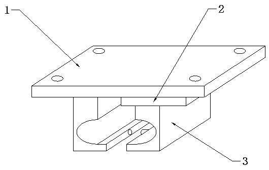
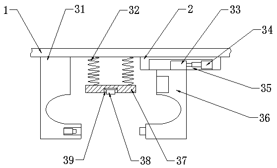
[0020] Specific implementation method: when in use, the user first uses the external fixing bolts to fix the fixed plate 1, and then the user operates the external device to make the fixed plate 1 move downward, and the downward movement of the fixed plate 1 drives the fixed block 2, the spring 32 and the fixed plate 1. Slot plate 31 moves downwards, and fixed block 2 moves downwards and drives slide block 33 to move downwards, and fixed block 2 moves downwards and drives mobile groove plate 36 to move downwards, and spring 32 moves downwards to drive magnetic plate 37 to move downwards, and the magnetic plate 37 moves downwards. The downward movement of the plate 37 drives the electric cylinder open switch 38 to move downward. When the magnetic plate 37 moves downward to the upper side of the tubular part, the tubular part moves upward under the magnetic attraction force of the magnetic plate 37 and triggers the electric cylinder open switch 38. Then the electric cylinder 34 w...


PUM


Abstract

The invention provides a simple industrial mechanical clamp tool. The simple industrial mechanical clamp tool comprises a fixing plate, a fixing block, a fixed grooved plate, springs, a slider, an electric cylinder, a sliding groove, a moving grooved plate, a magnetic plate, an electric cylinder starting switch and a rectangular groove, wherein the fixing block is installed at the lower end of thefixing plate, the fixed grooved plate is installed on the left portion of the lower end face of the fixing plate, the springs are fixed to the right side of the fixed grooved plate, the magnetic plate is installed at the lower ends of the springs, and the rectangular groove is formed in the middle of the lower end face of the magnetic plate; the electric cylinder starting switch is installed in the rectangular groove, the sliding groove is formed in the lower end face of the fixing block, the electric cylinder is fixed to the right end face in the sliding groove, the slider is installed at the left end of the electric cylinder, and the moving grooved plate is welded to the lower end of the slider. The design achieves the function of clamping a tubular part, the clamp tool is convenient touse and operate, the function of clamping the tubular part is achieved, the clamping effect is excellent, and the reliability is high.

Description

technical field [0001] The invention is a simple clamping device for industrial machinery, which belongs to the field of mechanical equipment. Background technique [0002] Industrial machinery refers to the mechanical equipment used in the process of industrial construction and industrial manufacturing to replace or assist human labor, collectively referred to as industrial machinery. During mechanical processing, it is often necessary to clamp tubular parts. The existing industrial When the mechanical clamp is used to clamp the tubular part, the clamping effect is poor. When the tubular part is clamped and moved, it is easy to fall, which will damage the tubular part and affect the processing progress. Contents of the invention [0003] Aiming at the deficiencies in the prior art, the purpose of the present invention is to provide a simple clamping device for industrial machinery to solve the problems raised in the above-mentioned background technology. The present inven...

Claims


Application Information

Patent Timeline
Patent Type & Authority Applications(China)
IPC IPC(8): B23Q7/04B25J15/02B25J13/00
Inventor 从云敬
Owner 从云敬
Why Eureka
Try Eureka