Injection mold for automobile trims

A technology for automotive trim strips and injection molds, applied in the field of injection molds, can solve problems such as affecting production efficiency and difficulty in picking up parts, and achieve the effects of low production cost, improved production efficiency, and smooth demoulding.

Pending Publication Date: 2018-11-16
NINGBO SWELL IND CO LTD
View PDF0 Cites 3 Cited by
  • Summary
  • Abstract
  • Description
  • Claims
  • Application Information

AI Technical Summary

Problems solved by technology

The buckle position of the car trim is narrow and needs to cooperate with the slanted ejector pin of the ejection mechanism. In order to ensure the strength of the slanted thimble, the width of the slanted thimble is usually consistent with the width of the U-shaped groove at the buckle position, and the slanted ejector needs to be extended. The two buckles

Method used


Image

  • Injection mold for automobile trims
  • Injection mold for automobile trims
  • Injection mold for automobile trims

Examples


Embodiment 1

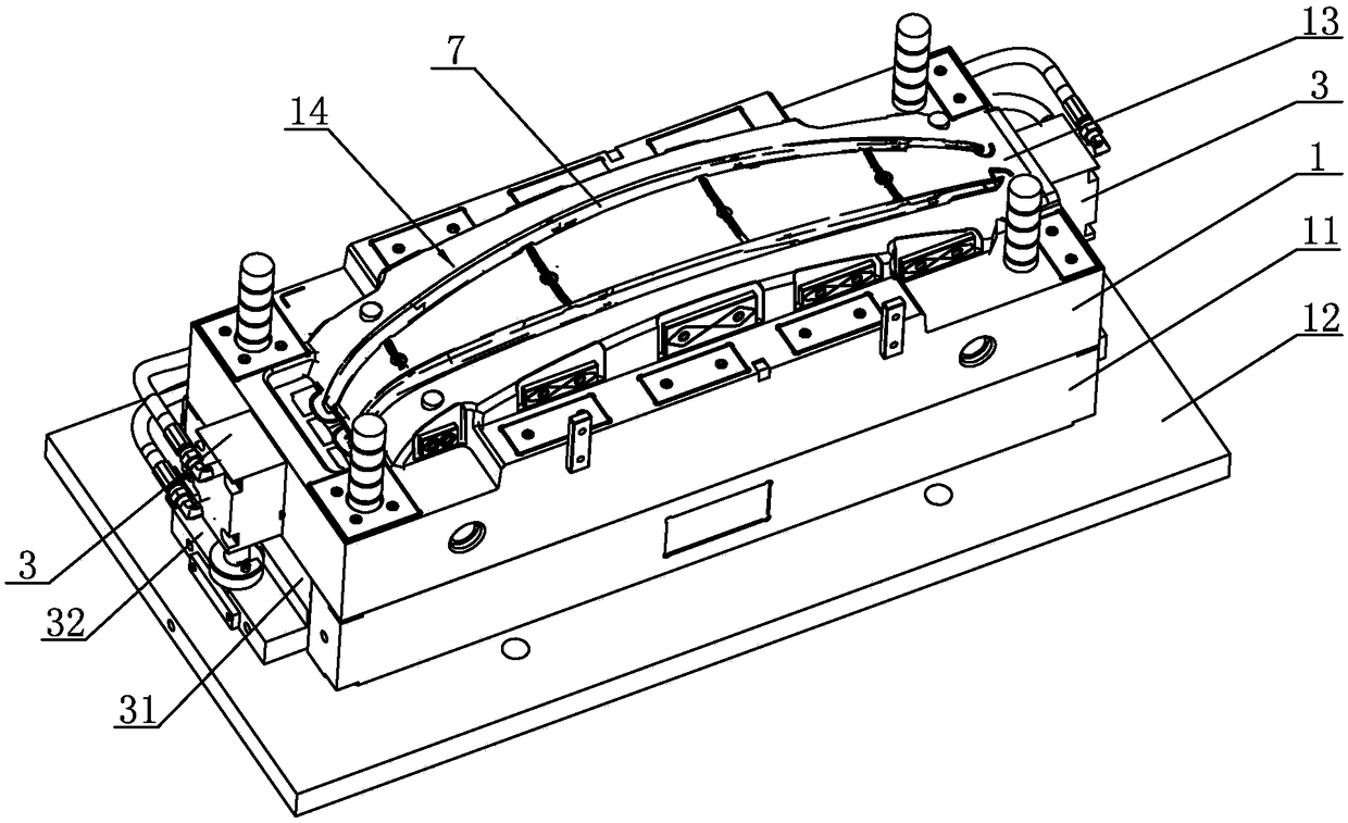
[0025] The automobile decorative strip injection mold of embodiment 1, such as Figure 3 to Figure 9As shown, it includes a movable template assembly and a fixed template assembly. The movable template assembly includes a movable template 1, a mold foot 11 and a movable mold fixed plate 12 arranged up and down. The top of the movable template 1 is provided with a movable mold core 13, and the movable mold core 13 The top is provided with a first cavity 14, and an ejection mechanism is provided between the movable template 1 and the movable mold fixed plate 12. The fixed template assembly includes a fixed template 2 arranged up and down, a hot runner mounting plate 21 and a fixed mold fixed plate 22. The hot runner assembly 23 is installed on the channel mounting plate 21, the top of the fixed template 2 is provided with a fixed mold core 24, and the top of the fixed mold core 24 is provided with a second cavity 25. On the formwork assembly, the first cavity 14 and the second c...

Embodiment 2

[0028] The difference between the automobile molding injection mold of embodiment 2 and embodiment 1 is that in embodiment 2, as shown in the figure, the driving mechanism includes a movable block 41, a striker 42, a reset block 43 and a mounting seat 44, and the mounting seat 44 is set Between the thimble fixed plate 31 and the thimble bottom plate 32, the mounting seat 44 is fixed on the thimble fixed plate 31, the movable block 41 is installed on the mounting seat 44 through a rotating pin 4, and the reset block 43 is arranged under the movable block 41, resets The block 43 is fixed on the movable mold fixed plate 12 by screws, and one side of the movable block 41 is provided with a concave first groove 45, and the bottom end of the accelerating thimble 5 is integrally provided with a first radial boss 51, and the first diameter Extend into the first groove 45 toward one side of the boss 51, the other side of the first radial boss 51 is inserted with the anti-rotation pin 46...


PUM


Abstract

The invention discloses an injection mold for automobile trims. The ejection mechanism of the injection mold comprises an ejection cylinder, an ejector pin fixing plate, an ejector pin base plate, a plurality of oblique ejector pins, a plurality of straight ejector pins and a plurality of accelerated ejection units, wherein each accelerated ejection unit comprises an accelerated ejector pin and adriving mechanism; the accelerated ejector pins are vertically mounted on the ejector pin fixing plate; each oblique ejector pin, each straight ejector pin and each accelerated ejector pin are arranged to simultaneously pass through the ejector pin fixing plate, a movable mold plate and a movable mole core, respectively; the top ends of each oblique ejector pin, each straight ejector pin and eachaccelerated ejector pin separately face a mold cavity; the top end of each oblique ejector pin faces a buckle on the mold cavity; one accelerated ejector pin is arranged beside each oblique ejector pin; and the driving mechanisms are mounted on the ejector pin fixing plate to drive the accelerated ejector pins to move up and down. Since a injection-molded part is ejected out through cooperation among the accelerated ejection units, the oblique ejector pins and the straight ejector pins, the design strength of the inclined ejector pins can be ensured, the smooth release of the injection-moldedpart can be ensured, the injection-molded part can be easily taken out, and production efficiency is improved.

Description

technical field [0001] The invention relates to an injection mold, in particular to an injection mold for automobile decorative strips. Background technique [0002] As the main exterior trim parts of automobiles, automobile decorative strips are more and more favored by consumers and are widely used in automobiles. Automotive moldings are usually injection molded and installed on the car by snap fit. Injection molds generally include a movable template and a fixed template. The movable template is provided with an ejection mechanism. After the automotive trim is injected, the ejector mechanism ejects the injection molded part from the movable mold core. The overall car trim is a slender structure, figure 1 For the rear view of a common car trim, figure 2 It is a cutaway view of a buckle position, figure 1 and figure 2 Among them, 1 is buckle. The buckle position of the car trim is narrow and needs to cooperate with the slanted ejector pin of the ejection mechanism. ...

Claims


Application Information

Patent Timeline
IPC IPC(8): B29C45/26B29C45/40
CPCB29C45/26B29C45/401
Inventor 罗旭强顾兴伟毛武杰
Owner NINGBO SWELL IND CO LTD
Why Eureka
Try Eureka