Intelligent locking device and system

A locking device and intelligent technology, applied in the field of intelligent locks, can solve problems such as poor reliability

Active Publication Date: 2018-11-16
常州电子研究所有限公司
View PDF5 Cites 0 Cited by
  • Summary
  • Abstract
  • Description
  • Claims
  • Application Information

AI Technical Summary

Problems solved by technology

[0004] In view of this, the object of the present invention is to provide an intelligent locking device and system to alleviate the technical problem of poor reliability of the intelligent locking device in the prior art

Method used


Image

  • Intelligent locking device and system
  • Intelligent locking device and system
  • Intelligent locking device and system

Examples


Embodiment 1

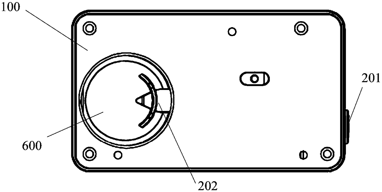
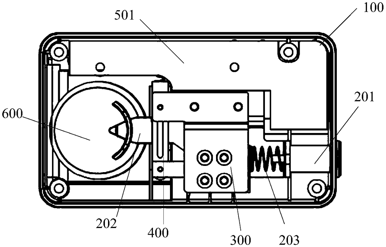
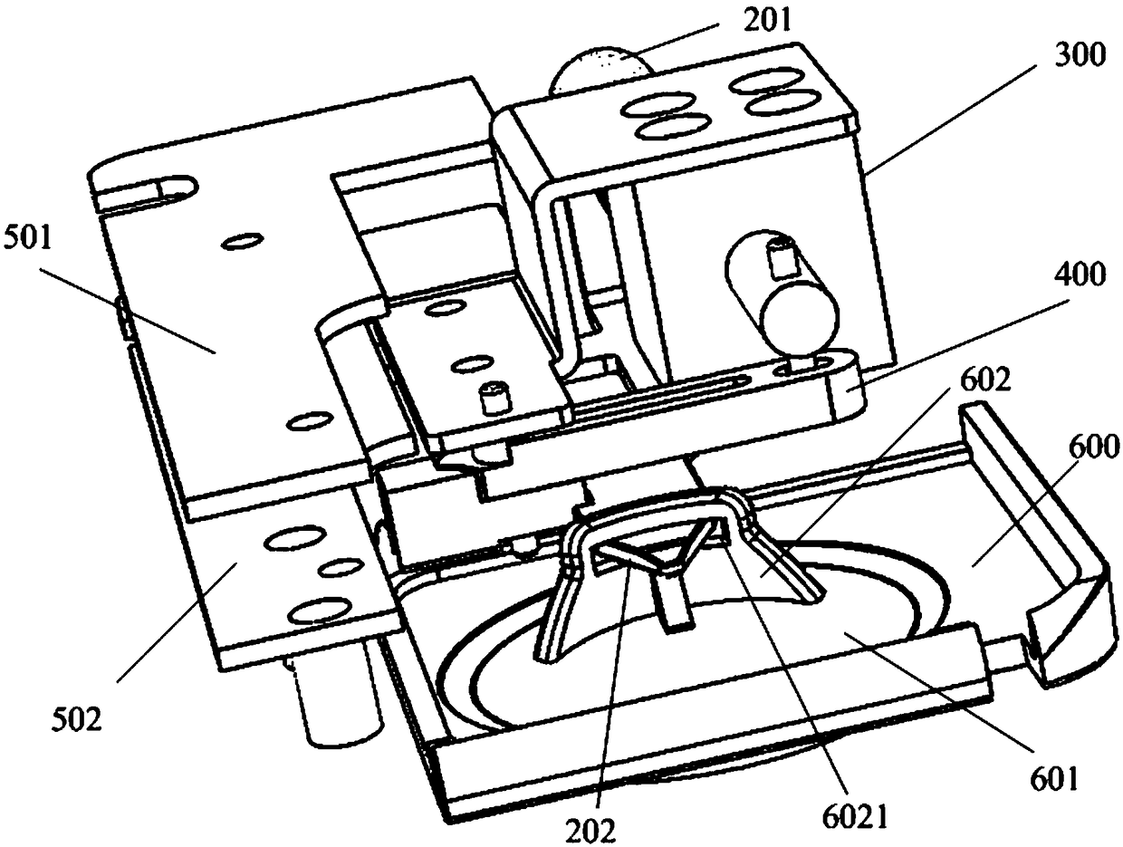
[0034] like Figure 1 to Figure 4 As shown, the embodiment of the present invention provides an intelligent locking device, which can be applied to electric equipment, especially to a ring network cabinet of an electric power system, including: a housing 100, a locking assembly, a driving assembly 300, and a lever assembly 400;

[0035] The above-mentioned locking assembly includes a lock ejector rod 201 and a lock tongue 202; the above-mentioned lock ejector rod is connected to the above-mentioned lock tongue, the top of the above-mentioned lock tongue is connected to the bottom of the above-mentioned lock ejector rod, and the bottom of the above-mentioned lock tongue is used to cooperate with the operation of the top cover 600. The above-mentioned lock ejector rod is arranged on the above-mentioned housing in a telescopic manner, and the above-mentioned lock ejector rod has a tendency to be far away from the above-mentioned lock tongue;

[0036] Further, in one embodiment, t...

Embodiment 2

[0073] Such as Figure 5 and Figure 6 As shown, the embodiment of the present invention provides an intelligent locking system, including: a key 20 and the intelligent locking device 10 as described in Embodiment 1, the key is matched with the above-mentioned intelligent locking device; The battery inside the key shell, the switch (also called power supply button) outside the key shell, and the pin 21 outside the key shell.

[0074] The casing of the above-mentioned intelligent locking device is provided with a key socket 103 matching the above-mentioned pins, and the key is connected to the circuit board of the intelligent locking device through the pins and the key socket.

[0075] Specifically, the housing includes a first housing 101 and a second housing 102, the first housing and the second housing are connected in a detachable manner, which is convenient for disassembly, maintenance, inspection, replacement of parts, etc.; the housing can play The function of protecti...


PUM


Abstract

The invention provides an intelligent locking device and system, relates to the field of intelligent locks, aims at relieving the problem of poorer reliability existing in an intelligent locking device in the prior art, and can improve the reliability and safety of the intelligent locking device. The device comprises a housing, a locking assembly, a driving assembly and a leverage assembly; the locking assembly comprises a lock jacking rod and a spring bolt; the lock jacking rod is connected with the spring bolt, the top of the spring bolt is connected with the bottom of the lock jacking rod,and the bottom of the spring bolt is used for cooperatively operating a jacking cover; the lock jacking rod can be telescopically arranged on the housing, and the lock jacking rod has the tendency ofgetting away from the spring bolt; the driving assembly is arranged on the housing; the leverage assembly is arranged in the housing, and the leverage assembly is in transmission connection with the driving assembly; when the intelligent locking device is in a locking state, the locking assembly is locked by the leverage assembly; when the intelligent locking device is in an unlocking state, the leverage assembly is separated from the locking assembly.

Description

technical field [0001] The invention relates to the technical field of intelligent locks, in particular to an intelligent locking device and system. Background technique [0002] At present, the existing intelligent locking device usually uses an electromagnet to directly drive the electromagnetic deadbolt to unlock. This method has the following disadvantages: 1. After the electromagnetic lock ejector rod is pressed, it cannot be completely locked, and there is a risk of rebound; 2. In order to provide a larger electromagnetic force, the volume of the electromagnet is usually made larger, so the power consumption is also large. [0003] To sum up, the traditional intelligent locking device has the problem of poor reliability. Contents of the invention [0004] In view of this, the object of the present invention is to provide an intelligent locking device and system, so as to alleviate the technical problem of poor reliability existing in the intelligent locking device i...

Claims


Application Information

Patent Timeline
IPC IPC(8): E05B47/02E05B47/00E05B17/20E05B15/10E05B15/14E05B15/00
CPCE05B15/00E05B15/10E05B15/14E05B17/2007E05B47/0002E05B47/02
Inventor 阮明徐新法王文银包大凤
Owner 常州电子研究所有限公司
Why Eureka
Try Eureka