A kind of semiconductor power device and its manufacturing method

A technology of power devices and semiconductors, applied in semiconductor devices, semiconductor/solid-state device manufacturing, semiconductor/solid-state device components, etc., can solve problems such as poor reliability of curved structures

Active Publication Date: 2021-08-24
天津中科先进技术产业有限公司
View PDF5 Cites 0 Cited by
  • Summary
  • Abstract
  • Description
  • Claims
  • Application Information

AI Technical Summary

Problems solved by technology

[0003] In view of this, the object of the present invention is to provide a semiconductor power device and its manufacturing method to alleviate the technical problem of poor reliability of the curved structure in the prior art

Method used


Image

  • A kind of semiconductor power device and its manufacturing method
  • A kind of semiconductor power device and its manufacturing method
  • A kind of semiconductor power device and its manufacturing method

Examples


Embodiment 1

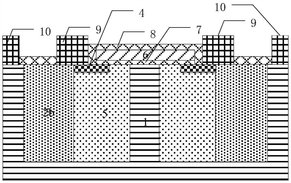
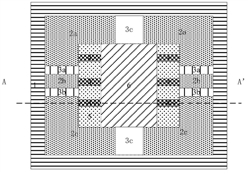
[0042] see figure 1 and figure 2 , a cross-sectional view and a top view of a semiconductor power device provided by an embodiment of the present invention. A semiconductor power device provided by an embodiment of the present invention includes: an N-type substrate, an N+ region 1, a P-body region 5, a PN alternating superjunction region, an N+ source region 4, a gate oxide layer 7, and a polysilicon gate 6 , Dielectric layer isolation 8, device source metal 9 and device drain metal 10. Wherein, the N+ region is an electron drift region composed of a central region, a bottom region and a side region. The cross-section of the side area is "mouth", the cross-section of the central area is "one", located in the center of the side area, and the bottom area is square, located at the bottom of the device.

[0043] The top of the N-type substrate is connected to the bottom edge region of the N+ region, the inner surface of the N+ region extends to the central region to form a P-...

Embodiment 2

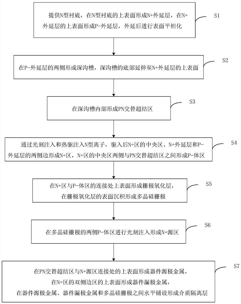
[0054] see image 3 , a flowchart of a method for manufacturing a semiconductor power device provided by an embodiment of the present invention. A method for manufacturing a semiconductor power device provided by an embodiment of the present invention includes the following steps:

[0055] Step S1: providing an N-type substrate, forming an N+ epitaxial layer on the upper surface of the N-type substrate, forming a P- epitaxial layer on the upper surface of the N+ epitaxial layer, and performing surface planarization after epitaxy. see Figure 4 , a product schematic diagram of step S1 in the method for manufacturing a semiconductor power device provided by an embodiment of the present invention.

[0056] Step S2: forming deep trenches on both sides of the P- epitaxial layer, the bottom of the deep trenches extending to the upper surface of the N+ epitaxial layer. see Figure 5 , a product schematic diagram of step S2 in the method for manufacturing a semiconductor power dev...


PUM

PropertyMeasurementUnit
widthaaaaaaaaaa

Abstract

The invention provides a semiconductor power device and a manufacturing method thereof, relating to the technical field of semiconductor integrated circuits, comprising: an N-type substrate, an N+ region, a P-body region, a PN alternating superjunction region, an N+ source region, and a gate oxide layer , polysilicon gate, dielectric layer isolation, device source metal and device drain metal. Among them, the PN alternating superjunction region is arranged alternately by the P+ layer and the N+ layer at longitudinal intervals, and the side of the P-body region between every adjacent two N+ source regions on the same side of the central region of the N+ region is provided with the first N+ layer and a second N+ layer; and a third N+ layer is arranged between the central area and the side area of ​​the N+ area. This technical solution alleviates the technical problem of poor structural reliability existing in the prior art, ensures the conduction performance of the device, improves the bearing strength of the longitudinal deformation of the semiconductor power device, and increases the bending tolerance of the semiconductor power device, making it It is protected from damage when subjected to mechanical deformation, improves the reliability of the device structure, and has simple manufacturing process and low manufacturing cost.

Description

technical field [0001] The invention relates to the technical field of semiconductor integrated circuits, in particular to a semiconductor power device and a manufacturing method thereof. Background technique [0002] At present, since entering the 21st century, "flexible and stretchable electronic devices" have entered a stage of rapid development. Due to their superior mechanical properties, flexible and stretchable electronic devices have great technical advantages and broad application prospects in many traditional and emerging fields such as health monitoring, medical implants, artificial skin, and human-computer interaction. However, currently widely available electronic materials, especially semiconductor materials, are often brittle and non-stretchable, making it difficult to be directly applied to flexible and stretchable electronic devices. In the process of realizing the present invention, the inventors found that there are at least the following problems in the ...

Claims


Application Information

Patent Timeline
Patent Type & Authority Patents(China)
IPC IPC(8): H01L29/06H01L29/78H01L23/00H01L21/336
CPCH01L23/562H01L29/0634H01L29/66681H01L29/7816
Inventor 储团结王海韵丛艳欣李亚娜
Owner 天津中科先进技术产业有限公司
Why Eureka
Try Eureka