Light-emitting door-free passage with good heat dissipation effect

A technology with heat dissipation effect and pass, applied in the field of building decoration, can solve the problems of inconvenient installation and disassembly, poor heat dissipation of LED lamps, slow heat conduction speed, etc., to reduce service life, achieve output light intensity and softness, and good heat dissipation effect. Effect

Active Publication Date: 2018-11-16
浙江卡福曼木业有限公司
View PDF3 Cites 1 Cited by
  • Summary
  • Abstract
  • Description
  • Claims
  • Application Information

AI Technical Summary

Problems solved by technology

In the lobby of large hotels and large restaurants, you can often see the decorative structure of space division through the pass. In order to meet the aesthetic and practical requirements of the pass in the existing lobby, LED lights are usually set on the top or both sides of the pass. Whether installing LED lanterns or LED lights on the pass, the LED lamps are installed directly on the pass, and the installation of the LED light on the pass requires a lot of screws, which is inconvenient to install and disassemble; LED lights After a long time of use, a lot of heat will be generated. The heat dissipation of the existing LED lamps on the pass is conducted through the air inside the lamp housing and then dissipated by the heat radiation of the lamp housing. This method of heat dissipation is due to the lack of air circulation inside the lamp housing to reduce the heat conduction speed. Slow, resulting in poor heat dissipation of LED lights, serious attenuation, and reduced lifespan
[0003] Therefore, the LED lights currently installed on the pass have the problems of inconvenient installation and disassembly, slow heat conduction speed, poor heat dissipation effect and short service life.

Method used


Image

  • Light-emitting door-free passage with good heat dissipation effect
  • Light-emitting door-free passage with good heat dissipation effect
  • Light-emitting door-free passage with good heat dissipation effect

Examples


Embodiment Construction

[0027] The present invention will be further described below in conjunction with the accompanying drawings and embodiments, but not as a basis for limiting the present invention.

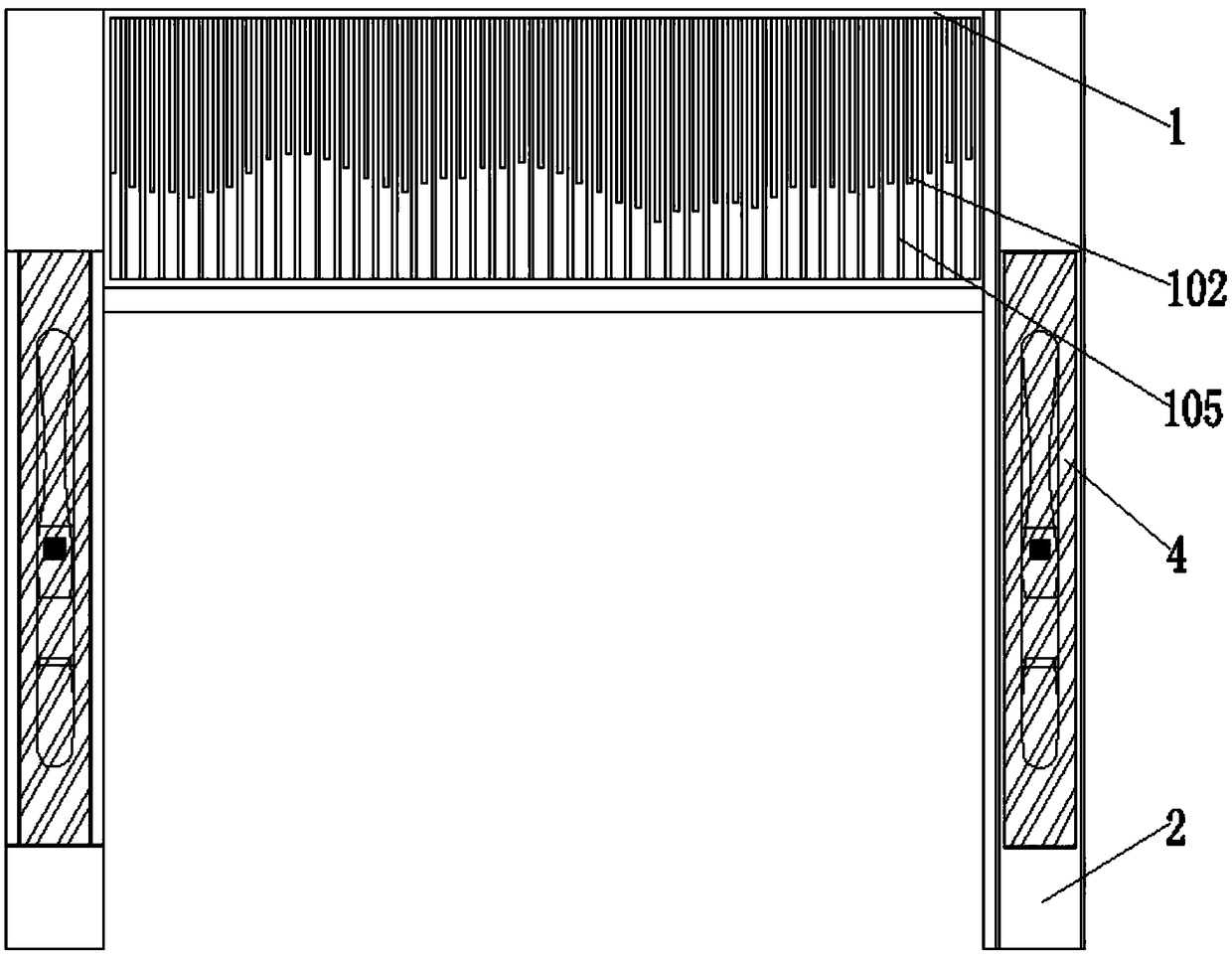
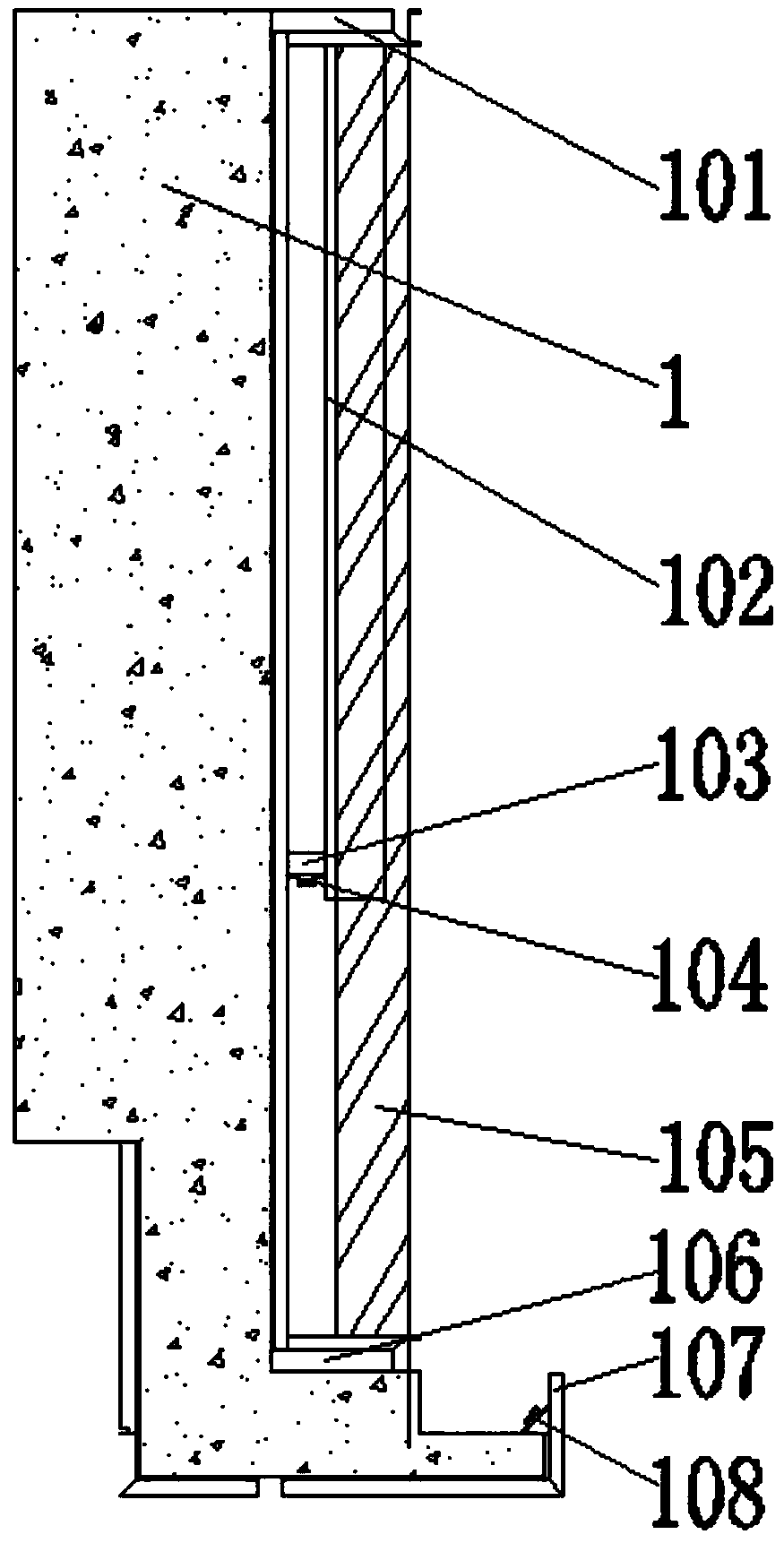
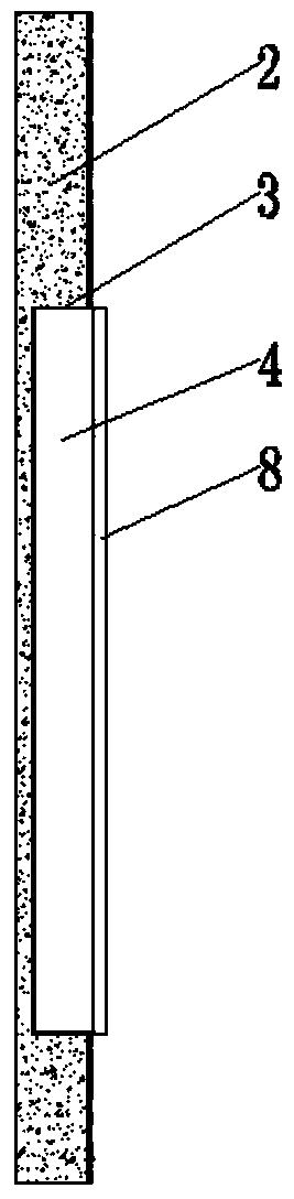
[0028] like figure 1 The light-emitting pass with good heat dissipation effect shown includes the upper pass 1 and the two ends of the upper pass such as image 3 Shown side pass 2; Side pass is provided with installation groove 3, and the top and bottom of installation groove are provided with several groups such as Figure 5 As shown in the arc-shaped positioning groove 301, a horizontal chute 302 is provided at the positioning and fixing groove on the side mouth; a lamp housing 4 is provided in the installation groove, and two ends of the lamp housing are provided with matching arc-shaped positioning grooves such as Image 6 As shown in the arc positioning block 303, the arc positioning block passes through as Figure 4 The cooperation between the slide plate 304 shown and the transverse slide ...


PUM


Abstract

The invention relates to the technical field of building decoration, and particularly discloses a light-emitting door-free passage with a good heat dissipation effect. The light-emitting door-free passage comprises an upper door-free passage body (1) and side door-free passage bodies (2); mounting grooves (3) are formed in the side door-free passage bodies, arc-shaped positioning grooves (301) areformed in the mounting grooves, and the side door-free passage bodies are provided with transverse sliding grooves (302); lamp shells (4) and arc-shaped positioning blocks (303) are arranged in the mounting grooves; the lamp shells (4) comprise rectangular bottom shells (401) and arc-shaped mounting parts (402); the rectangular bottom shells are provided with rectangular cavities (403); the rectangular cavities are internally provided with heat dissipation fans (404), and heat dissipation pieces (5) are arranged on the sides of the rectangular cavities; and reflective hoods (6) are arranged on the surfaces of the arc-shaped mounting parts, the reflective hoods are provided with lamp discs (7) with LED lamp belts (709), and the lamp shells are provided with lampshades (8). The light-emitting door-free passage has the characteristics of convenient mounting and dismounting, high heat conduction speed, good heat dissipation effect and long service life.

Description

technical field [0001] The invention relates to the technical field of building decoration, in particular to a luminous pass with good heat dissipation effect. Background technique [0002] Pass is a common component of architectural decoration. As people love and pursue the spaciousness and openness of living space, pass has replaced the position of door more and more frequently, and evolved another way of space division. Improves the sense of space in the room. In the lobby of large hotels and large restaurants, you can often see the decorative structure of space division through the pass. In order to meet the aesthetic and practical requirements of the pass in the existing lobby, LED lights are usually set on the top or both sides of the pass. Whether installing LED lanterns or LED lights on the pass, the LED lamps are installed directly on the pass, and the installation of the LED light on the pass requires a lot of screws, which is inconvenient to install and disassemb...

Claims


Application Information

Patent Timeline
Patent Type & Authority Applications(China)
IPC IPC(8): E06B1/34F21V33/00F21V29/67F21V19/00F21V29/83F21Y115/10
CPCE06B1/34F21V19/001F21V29/67F21V29/83F21V33/006F21Y2115/10
Inventor 傅成
Owner 浙江卡福曼木业有限公司
Why Eureka
Try Eureka