Connecting structure of streetlamp body and support
A connection structure and bracket connection plate technology, applied in the field of lighting, can solve the problems of limited angle range for disassembly and assembly adjustment, angles that cannot be adjusted, and few applicable environments, etc., and achieve the effect of high adjustment angle, large adjustment range, and simple operation
- Summary
- Abstract
- Description
- Claims
- Application Information
AI Technical Summary
Problems solved by technology
Method used
Image
Examples
Embodiment 1
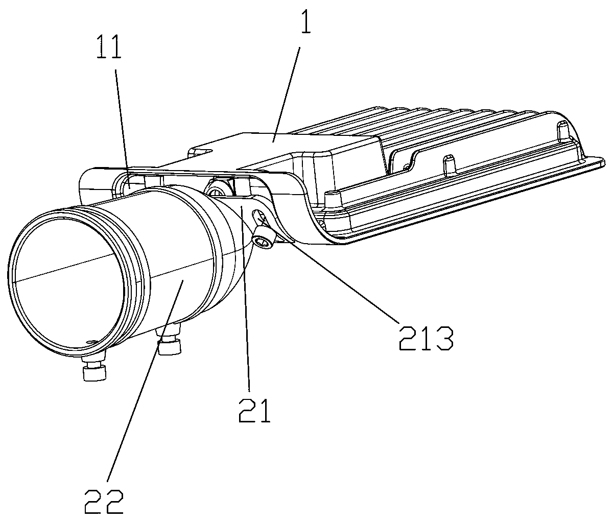
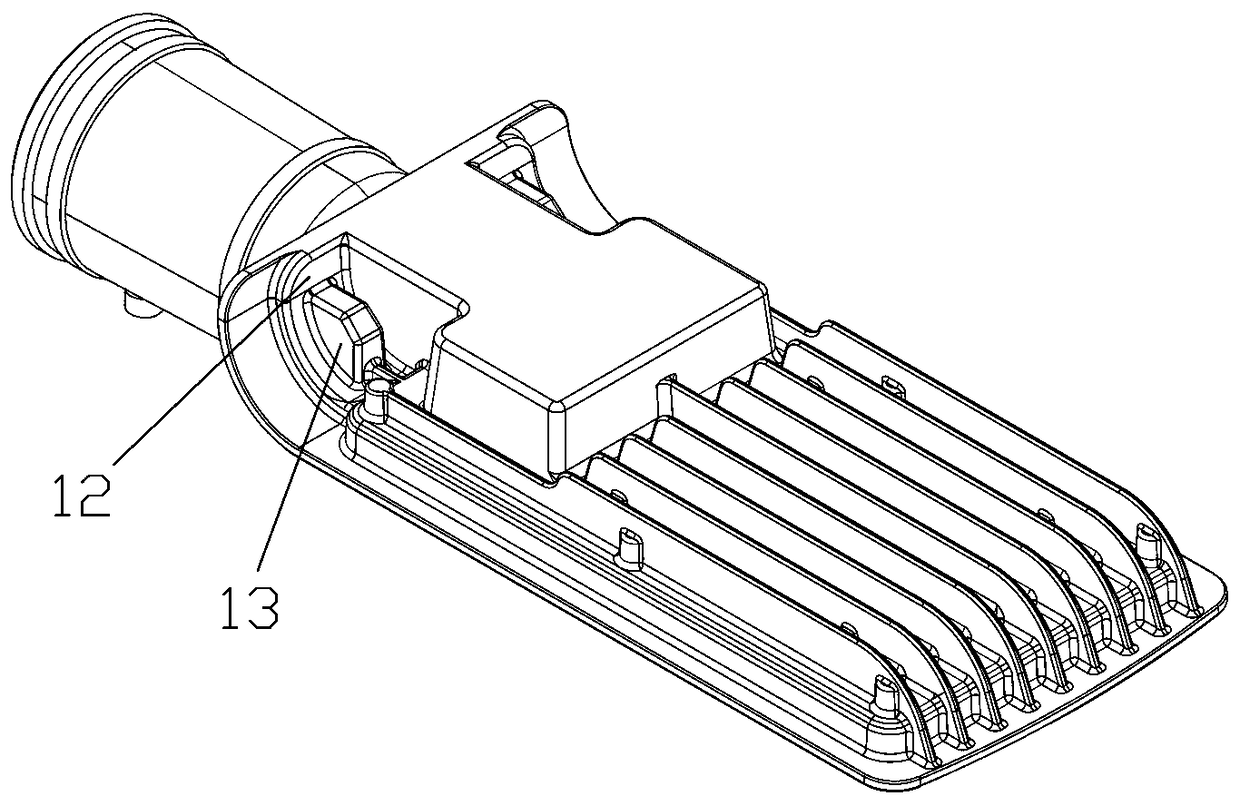
[0031] A connection structure between a lamp body and a bracket of a street lamp, comprising a lamp body 1 and a bracket 2 detachably connected to the lamp body, the rear end of the lamp body is provided with an arc-shaped lamp body connecting seat 11 or The arc-shaped lamp body connecting seat formed by sagging toward the lamp body in the up and down direction, the front end of the bracket is provided with an arc-shaped bracket connecting plate 21 adapted to connect with the lamp body connecting seat, and the bracket connecting plate is connected to the lamp body connecting seat. An adjustment component for facilitating the relative angle between the lamp holder and the bracket and for positioning and fixing is also provided between the lamp body connecting seats.
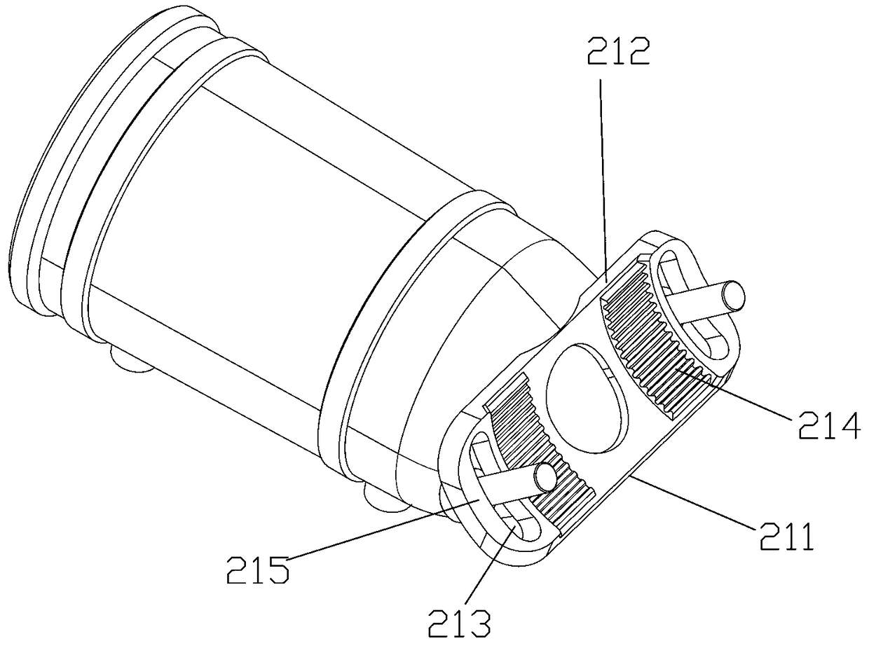
[0032] The bracket also includes a sleeve 22 as the bracket body, the front end edge 211 of the bracket connecting plate is located in the middle of the front end of the sleeve, the rear end edge 212 is close to th...
Embodiment 2
[0038] The difference from the above-mentioned embodiment is that the middle part of the lamp body connecting seat is indented by the lamp body connecting seat seat to form an installation cavity 112, and corresponding to the installation cavity is opened on the bracket connecting plate for communicating with the sleeve. There are holes in the installation cavity for the through holes of the electric wires, which can connect the electric wires in the casing to the lamp body, and then seal the holes and the connection positions of the electric wires through existing common seals on the market. The engaging racks are two groups symmetrically arranged on both sides of the installation cavity, and the two internal threaded holes are also symmetrically arranged on both sides of the installation cavity. The occlusal racks are symmetrically divided into two groups on both sides, which is also convenient for positioning and installation. If a single set of long racks is used, the meshi...
Embodiment 3
[0040]The difference from the above embodiment is that the engaging rack is a protruding tooth protruding from the surface of the connecting seat of the lamp body, and the two sides of the bracket connecting plate facing the surface of the lamp body are provided with the A limit boss 215 formed by thickening the body of the bracket connecting plate is adapted and positioned along the outer side of the protruding teeth, and the slotted hole is provided on the bracket connecting plate in a region corresponding to the limit boss. That is, the outer side of the engaging rack cooperates with the limiting boss to limit the position of the components. At the same time, the limit boss double can strengthen the connection strength of the slot connection position.
[0041] The positioning racks are two groups corresponding to two groups of the occlusal racks, and the length of the positioning racks is greater than the length of the occlusal teeth, and the outer end of the positioning ra...
PUM
 Abstract
Description
Claims
Application Information
 - R&D
- Intellectual Property
- Life Sciences
- Materials
- Tech Scout
- Unparalleled Data Quality
- Higher Quality Content
- 60% Fewer Hallucinations
Browse by: Latest US Patents, China's latest patents, Technical Efficacy Thesaurus, Application Domain, Technology Topic, Popular Technical Reports.
© 2025 PatSnap. All rights reserved.Legal|Privacy policy|Modern Slavery Act Transparency Statement|Sitemap|About US| Contact US: help@patsnap.com


